Tel/WeChat:
  Email:


 Home
HomeWhat is a Transition Fit? Applications, CNC Machining and Design

 Published:Aug 08,2026
The type of mechanical fit used can make or break an engineering project. A transition fit is a widely used category that specifies that the parts be neither too loose nor too tight. This particular set of specifications can be achieved through manufacturing operations such as CNC machining. This article contains everything that one needs to know about transition fit.
What Is a Transition Fit?
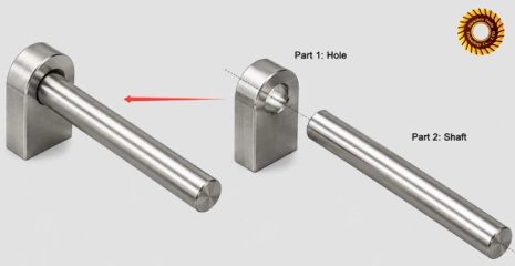
A transition fit is a kind of engineering design fit where the hole is slightly smaller than the shaft; it is designed to be the optimal fit for hand assembly and seamless alignment. Oftentimes in parts assembly, the hole and shaft may not fit ideally for the required application.
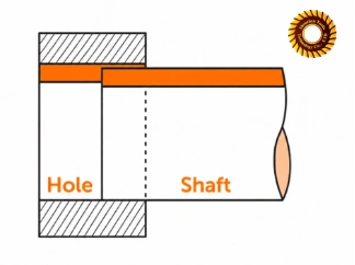
Is a Transition Fit Loose or Tight?
A transition fit is designed to be the middle ground in engineering fit (i.e., neither too loose nor too tight); however, it may be high in interference or clearance depending on the application and tolerance range. Here, the fit can either be free fit or close fit. In case of free fit, there will be more clearance and more tolerance (+0.2 mm to +0.5 mm in case of holes and -0.2 mm to -0.5 mm in case of shafts). On the other hand, the fit that has less clearance and tighter tolerance (+0.01 mm to +0.03 mm in case of holes and -0.01 mm to -0.03 mm for shafts) is known as close fit.
Transition Fit vs Clearance and Interference Fit
There are three major types of fits in mechanical engineering:
- interference fit
- clearance fit
- transition fit
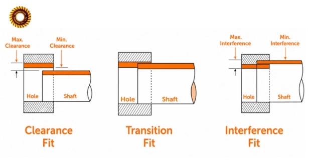
It all comes down to the application; a clearance fit grants greater freedom of movement for the engineering parts, while an interference fit has a tight fit requiring some force for the assembly of parts. A transition fit is a compromise between the two and is used in applications that require both temporary movement and secure positioning. Read the video for easier understanding.
Why Are Transition Fits Used?
Transition fits are used in high-precision applications that may require occasional disassembly. Since these types of fits have a low to zero clearance, they can provide structural stability as well as the possibility of mechanical movement.
Improve Positioning Stability
High clearance fits will be considered in this case. The space allowed for the shaft within the hole provides the freedom to move, but it sacrifices the stability in the position of the components. The parts will be easier to assemble and experience low friction, but they will also be moving almost constantly. This is why sometimes a transition fit will be more suitable because it provides stability without hindering mobility.
Allow Assembly and Disassembly
Regular maintenance of complex machinery may require the occasional disassembly and reassembly of the individual parts. Transition fits, being easier to assemble than interference fits, are best suited for this particular requirement. Although some amount of force may be required for joining the pieces in low clearance fits, there is still enough range of motion available for disassembling the pieces when required.
Where Are Transition Fits Used?
These types of engineering fits are used extensively in the automotive and industrial machinery industry. Some industries, such as the aerospace and medical device manufacturing industry, have unique requirements which are adequately accounted for using transition fits.
Positioning and Locating Components
Transition fits are commonly used when a component needs to be firmly positioned and capable of moving slightly when needed. Since positioning components typically have one fixed component and one movable tool, transition fits are well suited for them.
Shaft and Hub Connections
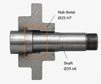
Shaft-and-hub connections are a common application for transition fits, since they need to hold the hub concentric to the shaft with minimal movement.
Removable Precision Assemblies
A transition fit is one that may typically be installed and disassembled by hand or by the use of light mechanical means like tapping. In circumstances where we require both stability and repeatability of position and also a removable joint, a transition fit can be considered.
What Are Common Transition Fit Tolerances?
The following table shows common clearance fit tolerances according to ISO standards using a 25 mm nominal size as a worked comparison:
|
Fit |
Max Clearance |
Max Interference |
Typical Tendency |
|---|---|---|---|
|
H6/js5 |
0.0175 mm |
0.0045 mm |
Very precise, relatively loose transition |
|
H6/k5 |
0.011 mm |
0.011 mm |
Precise, balanced transition |
|
H6/m5 |
0.005 mm |
0.017 mm |
Precise transition tending toward interference |
|
H7/js6 |
0.0275 mm |
0.0065 mm |
Relatively loose transition |
|
H7/k6 |
0.019 mm |
0.015 mm |
Common balanced transition |
|
H7/m6 |
0.013 mm |
0.021 mm |
Tighter transition |
|
H7/n6 |
0.006 mm |
0.028 mm |
Strongly tending toward interference |
|
H8/js7 |
0.0435 mm |
0.0105 mm |
Wider-tolerance, relatively loose transition |
|
H8/k7 |
0.031 mm |
0.023 mm |
Wider-tolerance balanced transition |
|
H8/m7 |
0.025 mm |
0.029 mm |
Wider-tolerance transition tending tighter |
H7/js6 vs H7/k6 vs H7/m6
With the same H7 hole, H7/js6 is the loosest, H7/k6 provides a more balanced transition fit, and H7/m6 is the tightest with the greatest tendency toward interference.
How to Choose the Required Fit?
Answer some questions for yourself. Do we need a tight fit or a loose fit? Will the required parts be constantly moving or will they be stuck in place? Which materials do you require and why? Is it necessary for you to put together and then take apart the various components? Is it essential to assemble and disassemble the parts during maintenance? By answering these questions, the desired fit can be chosen. Therefore, choosing the right fit by following these steps:
- Ensure the functions of the assembly
- Consider the Materials and Operating Conditions
- Determine the Acceptable Clearance and Interference
- Choose the Tolerance Combination
- Check Geometry and Surface Requirements
- Evaluate Manufacturing, Assembly, and Cost
In practice, if you need to design a new product including holes and shafts, you can apply common hole-basis system because both of shafts and holes are new. However, if you have had a shaft, and now you just need to design a hole, how can you choose the right transition fit? To make your shaft smoothly matched with the hole, you should determine what clearance or interference you is required and then select the mating hole tolerance.
For example, you have a standard pin, and the tolerance is Ø10 m6 dowel pin, if the max clearance and max interference of the H7/m6 can meet the design requirements, you should choose H7 hole tolerance,if not, choose other tolerance.
How Do You Calculate a Transition Fit?
A transition fit is calculated by comparing the size limits of the hole and the shaft, based on their tolerance grades. Each part has a maximum and minimum allowable size:
Hole: Hole max = Nominal + ES and Hole min = Nominal + EI
Shaft: Shaft max = Nominal + es and Shaft min = Nominal + ei
(ES/EI = upper/lower deviation of the hole; es/ei = upper/lower deviation of the shaft, capital letters for holes, lowercase for shafts.)
How to Calculate Maximum Clearance
Maximum clearance occurs when the hole is at its maximum allowable size and the shaft is at its minimum allowable size. It represents the largest possible positive gap between the mating parts within the specified tolerances. We can calculate it by:
Maximum Clearance = Hole max − Shaft min
Which is the maximum limit size of the hole minus the minimum limit size of the shaft.
How to Calculate Maximum Interference
Maximum interference occurs when the shaft is at its maximum allowable size and the hole is at its minimum allowable size. It represents the greatest possible overlap between the mating parts within the specified tolerances. This can be determined by:
Maximum Interference = Shaft Max − Hole Min
This is the difference between the upper limit of the shaft and the lower limit of the hole.
Simple H7/k6 Calculation Example
Let us take the nominal size as 25 mm for an H7/k6 fit. According to the ISO 286 standard:
- Hole (H7) limit diameter: Ø25.000 - Ø25.013 mm
- Shaft (k6) limit diameter: Ø25.002 - Ø25.011 mm
Using the above formulas, we have the following:
Maximum Clearance= 25.013 − 25.002
= +0.011 mm
Maximum Interference= 25.011 − 25.000
= +0.011 mm
Assembly clearance will be : -0.011 mm to +0.011 mm. Hence, the tightest (min) fit will be -0.011 mm and the loosest (max) will be +0.011 mm.
What Factors Affect a Transition Fit?
There are several factors that affect the performance of a transition fit assembly. These include the fit length and contact surface, thermal expansion, and also surface treatment. Here is an explanation of these effects:
Fit Length and Contact Area
Length of fit means the length at which there is contact between two engineering parts, whereas contact area means the area at which there is contact between two engineering parts. These factors are important because it affects the allowance gap between the shaft and hole pair because of added friction.
Material Thermal Expansion
Different materials act differently to changes in temperature. This is the reason why the thermal expansion of materials used in achieving an optimal transition fit needs to be considered. Should the shaft expand or contract depending on the environment that it is subjected to, then there could be changes in clearance values.
Surface Treatment
The surface finish and any machining process after the process (like plating, coating, or heat treating) may result in increased thickness or modifying the pre-determined size of the shaft or the hole. A coating applied after the fit dimension was recorded can affect the measurement just enough to change a slight clearance into a too-tight fit.
Tuofa CNC Machining for Transition Fits
The Tuofa CNC machining company offers precision and value compared to generic CNC machining companies. In the case of the Tuofa CNC machining company, they manufacture according to specifications with tolerances of ±0.0002 inches or 0.005 mm in critical dimensions, while dimensions of size and location have ±0.005 inches (metals) or ±0.010 inches (plastics/composites) except when there are tighter tolerances specified on the print according to ISO 2768.
Machining the Hole to the Required Tolerance
Holes that will be used for a transition fit should be bored and reamed rather than just drilled because regular drilling will not be able to meet the tight tolerance range required for a transition fit. Among the CNC machining capabilities provided by Tuofa, boring and reaming are performed as finishing processes to achieve the desired hole size and smooth finish surface.
Machining the Shaft to the Required Tolerance
Shafts are usually roughly machined first and then finish machined to get the shaft in its required tolerance band. This process follows for all parts made by Tuofa's CNC machine because this process will enable the two stages of machining to be done separately and effectively.
Controlling Roundness and Surface Finish
Uniform roundness requires the right tools and properly calibrated equipment during both the turning and grinding operations. The typical machined surface finish of Tuofa is at least 125 Ra, and all the round corners are deburred.
How Should A Transition Fit be Specified on A Drawing?
These measurements must be specified according to universal standards such as ISO.
Specify the Hole and Shaft Tolerances
The drawing is expected to specify clearly the ISO tolerance class of both the hole and shaft parts, for example, H7/k6 can be specified as "Hole: ⌀25 H7" and "Shaft: ⌀25 k6".
Specify Surface Roughness and Entry Chamfers
Surface roughness will affect the actual behavior of assembly, despite being within the specified diameter range. It is important to make sure that any surface treatment that might be necessary, such as plating and heat treatment, is considered, as well as if the tolerance specified is applicable before or after treatment.
- Specify the required surface roughness: such as Ra 0.8 μm or Ra 1.6 μm
- Specify a lead-in chamfer on the shaft end: such as C0.5 × 45°
- Add a deburring note for critical fitting edges: such as Deburr mating edges
- Specify the chamfer size directly: such as 0.5 × 45°
Add Geometric Tolerances Only When Necessary
Geometric dimensioning and tolerancing (GD&T) can be applied whenever required in order to guarantee that the design is properly conveyed to the engineers. This may prevent any possible errors during the manufacturing process.Critical structures can be specified , for examples:
- Cylindricity: Used for long precision fitting surface
- Straightness: Prevents an oval cross-section from causing local binding.
- Straightness: Prevents a bent shaft from being unable to enter the hole.
Common Transition Fit Problems and Solutions
Some common problems arise where precisely machined parts, especially with low tolerances, are concerned.
The Parts Are Too Tight
If the components fit too tight, there may be an issue where the surface roughness is too high, or perhaps there is some kind of plating/coating done on the component. By measuring the tolerance of both the components again, one can identify the reason behind the problem.
Excessive Clearance After Assembly
Excessively tight fit between two assembled components implies that the hole or shaft has been made near the tight side of the tolerance range. It's also possible that parts may have worn down during the manufacturing process, in which case there may be the need for an alternative production approach.
The Dimensions Pass Inspection but the Parts Still Stick
When this occurs, it is an indication that either the surface finish or the roundness/straightness of the part influenced the fit. A shaft or hole can measure within its diameter tolerance at a few inspection points, but the slight variation of the part's shape or surface roughness can affect the fit.
Conclusion
Transition fits require precise control of both hole and shaft dimensions because small variations can change the assembly from clearance to interference. Tuofa reviews the required fit, machining process, surface condition, and inspection method before production to help maintain the specified tolerances from prototype to production parts.
FAQ
What is the difference between a slip fit and a transition fit?
Slip fits are clearance fits that have the shaft size smaller than the hole size, which means that there is free movement without any possibility of an interference fit. While, in a transition fit, the fit could either be an interference or a clearance based on where the components lie in their tolerance zones.
What are the disadvantages of transition fit?
Tolerance control is stricter for transition fit because of the high importance of not making it either too loose or too tight, hence increasing the cost of machining. Then, there's the element of uncertainty because the result is not known beforehand. The assembly pressure will vary from one component to another, while the assembly itself becomes very sensitive to temperature changes and finish because of tighter tolerances.
Is a transition fit suitable for moving parts?
Absolutely not. Transition fits are not meant for components which are supposed to be in motion continuously. It is mainly meant for static positioning where there is minimum to no movement at all. Clearance fits will suit well in those conditions where there is movement because there will always be clearance space.
Is H7 a Transition Fit?
No, H7 only means the tolerance of the hole. A transition fit must consist of shaft tolerance and hole tolerance, such as H7/js6, H7/k6, or H7/m6.
 What Is Thread Depth? Design and CNC Machining Guidelines for Accurate Threads