Tel/WeChat:
  Email:
 Home
HomeConcentricity in GD&T: Meaning, Tolerance, Inspection, and Machining Tips

 Published:Jan 15,2026
Geometry, designs, and tolerances are the primary requirements in manufacturing any part. Here, concentricity is one of the most important geometric terms, which means how the two central axis of two rotating parts are perfectly meeting. The common example of concentricity can be found in a car, where a tyre perfectly rotates with a shaft. For reliable applications, concentricity is the most important thing in GD&T. This article explains different aspects of concentricity with respect to GD&T.
What Is Concentricity in GD&T
In GD&T (Geometric Dimensioning and Tolerancing), concentricity means alignment of a part's axis with a datum axis. It measures whether all the median points of a part's cross-section fall within a cylindrical tolerance zone.
GD&T Concentricity Explained
The biggest purpose of concentricity in GD&T is to confirm if the material of a cylindrical part is uniformly distributed. During rotations, if the mass is unevenly distributed, it will cause vibrations during the application, which further leads to losses.
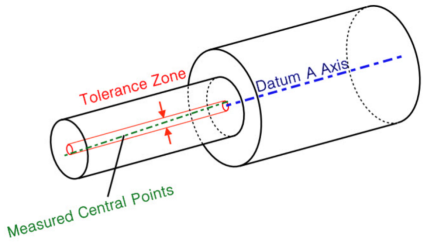
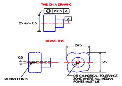
Here, in this figure, concentricity is focusing on all median points that are aligned perfectly with datum A axis.
Is Concentricity Still Used in GD&T?
It is used in very specific applications, such as aerospace and gyroscopes, etc., where precision is extremely important. It is removed from ASME Y14.5-2018 but is still used in ISO.
For Concentricity:
- ASME Y14.5-2018 recommends using runoutinstead of concentricity unless mass distribution is very critical.
- ISO standard considers concentricity as an ambiguous and difficult-to-control geometric characteristic. It recommends using coaxility, which is controlled through position tolerance and runout.
Why Concentricity Matters in Precision Parts
In precision parts, such as turbine blades in aerospace, concentricity has significant importance with respect to the performance of the part. It ensures the mass of the part is evenly distributed around a central point and all the median points are aligned correctly with the datum axis.
If the mass is not even in the part, it will shake and vibrate during the rotation. It can cause severe damage to the turbine blade and lead to loss of lives.
Concentricity Symbol in Drawing
In drawing, different symbols are used to present a specific dimension. For instance, ǁ means that two lines are parallel. In the same way, in drawing, concentricity is presented through a symbol.
Concentricity GD&T Symbol
Please see the following figure, which presents the concentricity symbol used in drawings.
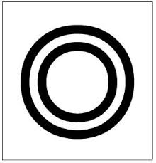
The symbol has two concentric circles:
- One presents the tolerance zone
- One presents datum A.
Symbol
- ◎presents concentricity in GD&T
- Indicates if all the median points are within the cylindrical tolerance zone
Location
- ◎is shown in the first block of a Feature Control Frame (FCF) on a drawing
- Attached to the diameter dimension of a cylindrical feature
- References a datum axis to control alignment.
- For instance, Ø20 ◎| 0.05 | A
Tolerance Datum
In GD&T, a single point or axis is used as a reference point to define locations, variations in the tolerances, and orientation of other points or features of the part. This point is called the Tolerance Datum.
Basic Concentricity Features
Basic concentricity features include:
- Geometric Characteristic
Concentricity measures the alignment of all the median points within a cylindrical tolerance with respect to the datum axis.
- Tolerance Value
It means the permissible variation in the alignment with the datum axis.
- Datum Reference
A baseline derived from a datum feature about which all the median points must be centred.
What Does Concentricity Tolerance Control in GD&T?
In simple words, conentricity tolerance controls how evenly mass is distributed in a part. In technical words, it controls the location of a feature's median axis relative to a datum axis.
What is Concentricity Tolerance Zone
The shape of the concentricity tolerance zone is cylindrical, which is centered on a datum axis. Within this zone, the median axis of the controlled feature must lie.
Concentricity Formula and Units
In the CMM software, concentricity is measured using the following formula:
Formula:
C = (Wmin / Wmax) * 100%
Here,
- C= concentricity
- Wmin= minimum wall thickness
- Wmax= maximum wall thickness
Units:
Different units are used with respect to the size of the part:
- Inches (in)
- Millimeter (mm)
- Micrometer (µm)
Common Acceptable Concentricity Limits
These are the concentricity limits with respect to different parts:
- For general machined parts:
0.05 – 0.1mm
- For precision parts:
0.02 – 0.05 mm
- For high-speed rotating parts, like motors:
0.005 – 0.02 mm
- For aerospace and gyroscopic components:
≤ 0.005 mm
Concentricity vs Runout and Position
Runout is often used instead of concentricity in technical drawings because it is relatively easier than concentricity. Position is another geometric characteristic used in GD&T.
Concentricity vs Circular Runout
- A single point or axis, used as a reference point to orient points of a part's other features, is called Concentricity.
- How much a surface wobbles during the rotation is measured through the circular runout.
|
Characteristic |
Concentricity |
Circular Runout |
|
Measurement approach |
Computational only |
Physical rotation with probe or sensor |
|
Inspection method |
CMM only |
Dial indicator or CMM during rotation |
|
Typical application |
Mass balance in high-speed rotating components |
Functional rotation accuracy (shafts, bearings) |
Concentricity vs Total Runout
- The measurement of a part's wobbling along the entire length during the rotation is called total runout.
Although it controls concentricity, it is still different than concentricity in some aspects:
|
Characteristic |
Total Runout |
Concentricity |
|
Measurement method |
Dial indicator or CMM while rotating the part |
CMM only |
|
Evaluation |
Entire surface, including roughness, straightness, etc. |
Derived median line |
|
Typical use |
Functional accuracy of shafts, bearing seats, and sealing surfaces |
Mass balance in high-speed rotating components |
Concentricity vs Position and Coaxiality
- Position controls the orientation of the axis, the location of the axis, and coaxility to a datum axis.
- Coaxiality means two or more surfaces share the same axis. It doesn't have a separate symbol in GD&T like concentricity.
Concentricity is a way to attempt to control coaxility. While position is another tool like runout to measure concentricity.
|
Characteristic |
Use Case |
Main concern |
|
Position |
Axis location is critical for assembly/fit |
Misalignment |
|
Concentricity |
Mass balance in high-speed rotation matters |
Vibration from uneven mass |
|
Coaxiality |
Multiple features must share one axis in function |
Uneven loading |
How to Measure Concentricity
Concentricity is not measured by using the traditional tools, but specific tools, like CMM and indicator gauges, are used.
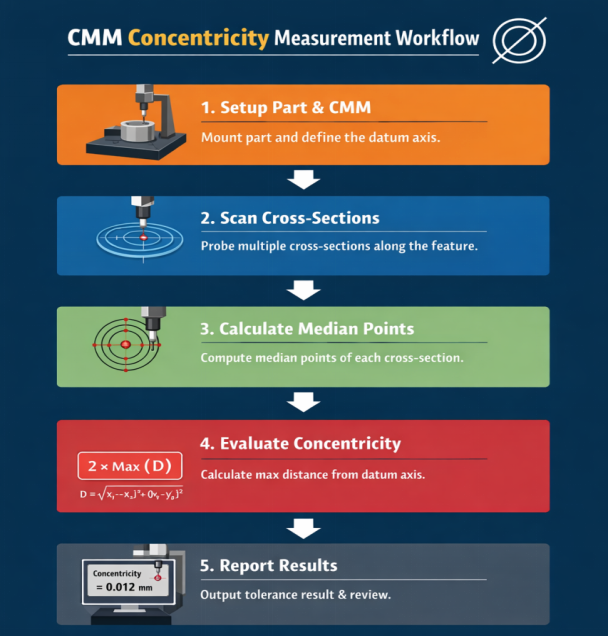
CMM Concentricity Measurement Workflow
The first step is to mount the part and then define the datum axis. The results of the measurement are shown on a screen at the end. Please see the following workflow chart for better understanding:
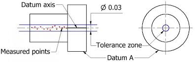
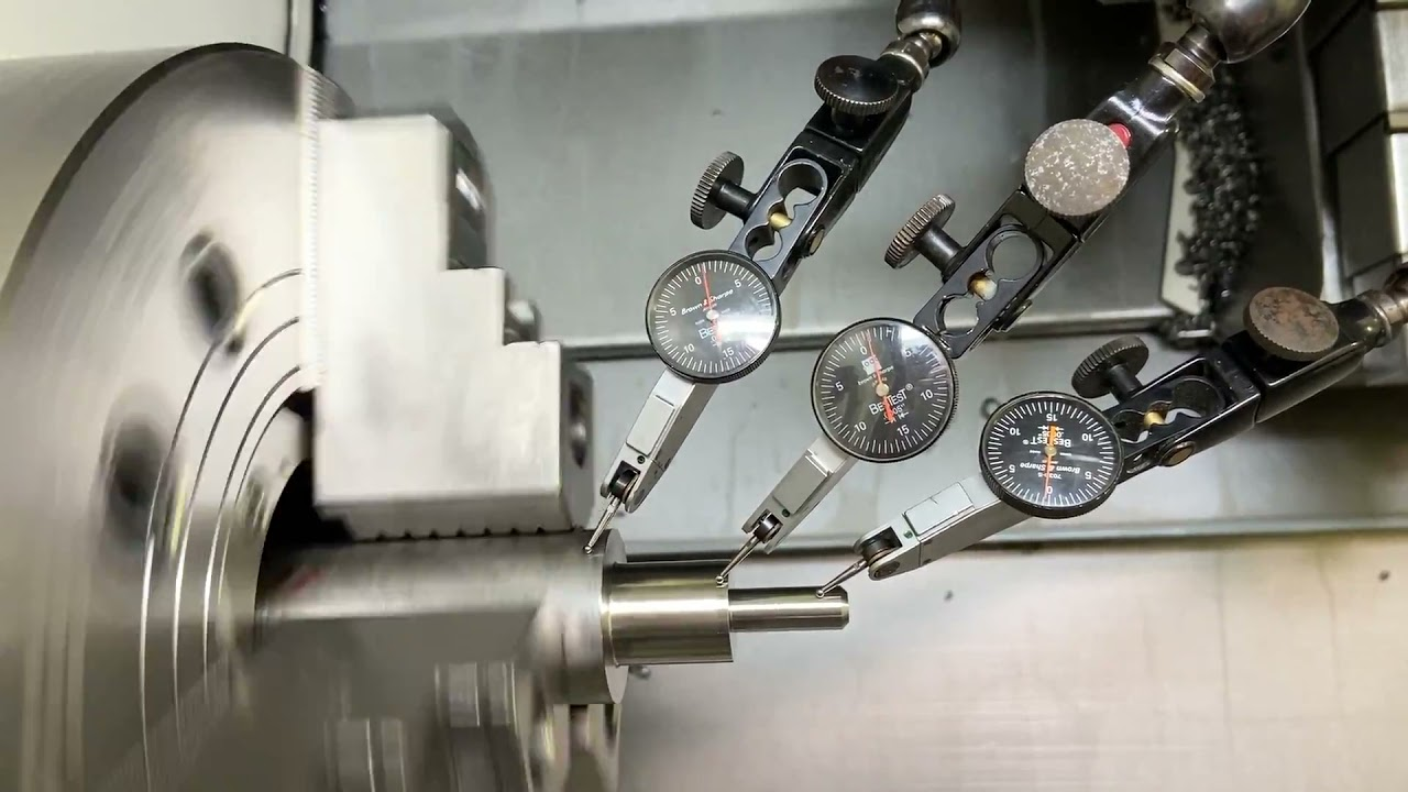
Dial Indicator Methods
To measure the concentricity using dial indicator methods, the following steps are performed:
- Establish datum axis
- Mount dial indicator
- Rotate part or gauge
- Record total indicator reading (TIR)
- Compare with tolerance
These are the concentricity gauges used for measuring concentricity:
- Fixed-type gauges
- Master-jig gauges (quick)
- Air gauges (non-contact)
What Tools Are Best for Checking Concentricity and Coaxiality?
- Coordinate measuring machine (CMM)
- Dial indicator
- Air gauges
- Coaxiality gauges
- Optical methods, such as using cameras
Concentricity in Real Parts and Industries
There are many industries where concentricity is considered critical and still used. In a machine, coaxility between two parts, like in a tyre and a shaft, plays a crucial role in the performance.
Precision Tubing and Medical Devices
Concentricity plays its role in:
- Catheters
- Fluid flow accuracy, like IV infusion tubing
- Guidewires and delivery systems
- Fitting and assembling medical devices
Safety in these parts is very crucial, which is controlled by concentricity. These parts are very small and have very thin walls. Concentricity ensures safety by preventing kinking, inaccurate flow control, and rupture. The concept behind this prevention is that the internal diameter remains perfectly aligned with the outer diameter, which is concentricity.
High Pressure Housings
High-pressure housings are cylindrical parts. They contain high internal pressure. Concentricity is required in the following areas in high-pressure housings:
- Hydraulic valve bodies
- Pressure vessels
- Oil and gas downhole tools
- Pump and compressor housings
Concentricity ensures even wall thickness in the entire length, which prevents stress concentration, seal failure, reduced burst pressure, and catastrophic safety risks.
Fluid Connectors
As the name gives a clue that they connect two or more pipe which carry liquid or high-pressure gases. Here, concentricity is required in:
- Medical luer connectors
- Pneumatic couplings
- Hydraulic fittings
- Fuel line connectors
Custom Precision Parts
When concentricity and coaxility in manufacturing the parts are required, TUOFA CNC precision machining experts stand tall due to its advanced CNC machines, expert workers, and fully updated inspection machines and tools. TUOFA makes sure the accurate assembly and smooth fluid flow in the parts. In-process and post-processing inspection is done at TUOFA to avoid any geometric and technical errors. For machining services for your projects when concentricity is required, come to TUOFA. We offer our services at cost-effective rates + shortest delivery times.
How CNC Machining Process Control for Concentricity
It is very difficult to machine parts for concentricity requirements if traditional cutting tools or operations are used. So, CNC machining is required here. But some areas that get affected during the CNC machining processes, such as:
- Spindle condition and alignment
- Tool-related factors
- Cutting force and workpiece material behaviour
- Work holding and fixturing
CNC Turning Concentric Parts
In the CNC turning process:
- The workpiece rotates
- The cutting tools remain stationary at their positions
This process provides tight control of dimensional tolerances and even mass distribution in the part. The concentricity in the following parts is maintained through the turning process.
- Stepped shafts
- Motor shafts
- Bushings and sleeves
- Bearing seats
CNC Milling Concentric Parts
In the CNC milling operation:
- The workpiece remains stationary
- But the cutting tools operate
This process is efficient in making the parts of complex geometries, and it stands tall when it is related to concentricity in the parts.
- Gearbox casings
- Pump housings
- Motor and servo housings
- Aerospace bores with precision brackets
These parts need concentricity, which is why a CNC milling operation is used.
In Process Inspection
To keep machining the parts perfectly with respect to concentricity, in process inspection is carried out, which helps in setting the following points:
- Detection of errors early
- Avoiding the scrap
- Correct offsets immediately
This in-process inspection is an important part of machining the parts when concentricity is required because once a part is manufactured, it is very difficult to find concentricity errors.
For in-process inspection, these tools are used:
- Dial-indicator check
- Touch probe
- Bore gauge for holes
Design Tips to Achieve Better Manufacturability
To achieve concentricity efficiently, this section provides some tips for designers and DFM engineers, like how to write in drawings and choose targets.
Use Concentricity Only When Necessary
Concentricity is very difficult to measure, so try to use its alternatives, which are given below. These alternatives are easy to measure and provide very close information, as concentricity does.
Alternatives:
- Position tolerance
- Circular or Total Runout
- Profile tolerance
Deign for Manufacturing
To achieve concentricity during manufacturing, follow these tips:
- Try to use single-setup machining
- Use proper workholding
- Choose the correct datum
- Minimize tool deflection
- Control thermal effects through some coolant
- Machining sequence matters
- Use in-process inspection
- Minimize reclamping and part handling
- Finish grinding or honing
Custom Design Tips
Customization may be required in parts, such as precision shafts, fluid connectors, etc., when the design is a little bit different from the standard. For custom designing, these are the tips to be followed for concentricity:
- Consider concentricity while designing the part
- Use uniform thickness in hollow parts
- Try to reduce thin, long, or asymmetric walls
- Do not use unnecessary tolerances
- Incorporate reference surfaces for fixturing
- Do not make designs very complex
Conclusion
In GD&T, concentricity is an important geometric characteristic. It measures mass distribution around a datum axis. Concentricity enhances the safety factor of a part by controlling the part's wobbling during rotation, so it prevents the part from rupturing. It is measured in mm or µm. Coordinate measuring machine and indicator gauges are used to measure this geometric concentricity. In modern manufacturing and designs, runout and position tolerance are preferred over concentricity because of the difficulty in measuring it. It is only used when the mass distribution is critical.
FAQs about Concentricity
What is the 3/2/h rule in GD&T?
It's a datum establishment rule, which uses three, two, and one contact points to fully constrain a part's six degrees of freedom.
How do you check concentricity?
Coordinate measuring machine (CMM) and indicator gauges are used to check concentricity.
What is concentricity vs runout?
Concentricity: it is the centre point of a part where all the median points are within the tolerance zone of a datum axis.
Runout: it is a way to check whether the part wobbles when it rotates.
What is considered acceptable concentricity?
According to the ASME standard, it is acceptable only when mass distribution is important. While the ISO standard considers it an ambiguous geometric characteristic.
What does the symbol ⌀ represent in GD&T?
The symbol ⌀ represents diameter in GD&T.
 Perpendicularity in GD&T: Important Geometric Tolerance Symbol