Tel/WeChat:
  Email:
 Home
HomePress Fit Tolerance Guide: How to Achieve Precision Machining

 Published:May 09,2025
Press fitting (also known as an interference fit) is a classic assembly technique where a slightly oversized part is pressed into a slightly undersized mating part, creating a firm joint through friction. Here is a complete guide of press fit tolerance and you would learn something new!
What Is Press Fit Tolerance?
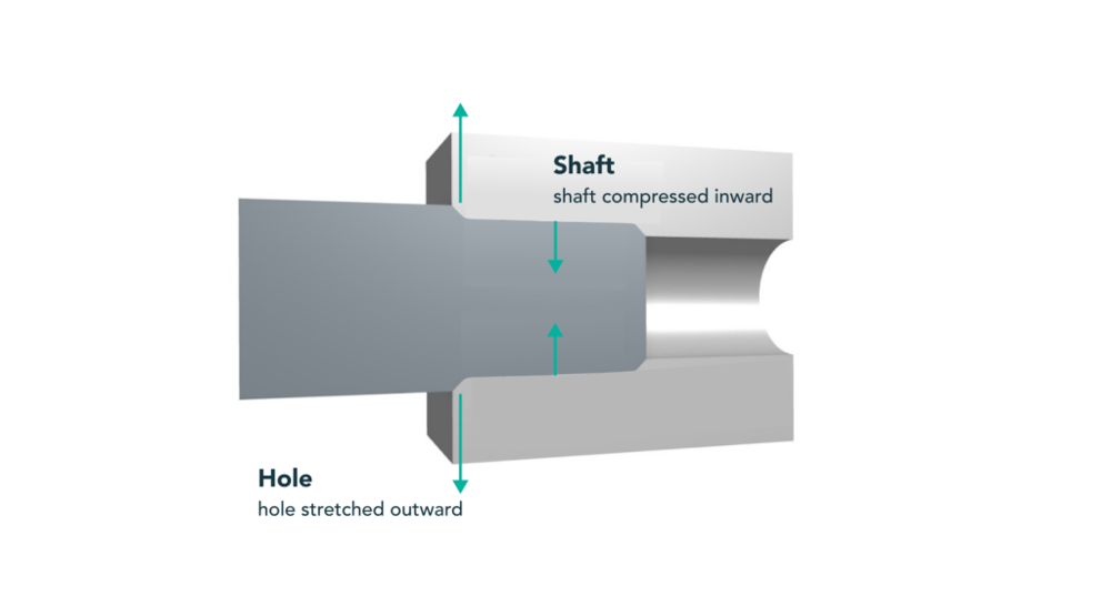
Press fit tolerance refers to the small dimensional difference between a shaft and its mating hole that creates an interference fit. The shaft is made slightly larger, so when pressed into the hole, frictional force holds the parts tightly. This technique allows secure assemblies without adhesives or fasteners.
Interference vs. Transition vs. Clearance Fits
These are three categories of engineering fits based on the shaft-hole size relationship:
|
Fit Type |
Description |
Common Use |
|
Clearance Fit |
Shaft < Hole; allows movement. |
Rotating or sliding parts |
|
Transition Fit |
Shaft ≈ Hole; light force fit. |
Accurate alignment, removable |
|
Interference Fit |
Shaft > Hole; firm, permanent fit. |
Bearings, gears, hubs |
Shaft-Basis vs. Hole-Basis Systems (ISO 286 quick view)
ISO 286 defines tolerance codes: uppercase letters (e.g., H) for holes, lowercase (e.g., p) for shafts. Hole-basis (e.g., H7/p6) keeps the hole constant while varying the shaft to control fit. Shaft-basis (e.g., h6/P7) does the opposite.
Rule-of-Thumb Ranges for Light, Medium, and Heavy Press Fits
There are some difference between light, medium, and heavy press fits:
|
Fit Type |
Interference (% of D) |
Typical Assembly |
Notes |
|
Light Press Fit |
0.05% |
Hand or arbor press |
Easy to assemble, removable |
|
Medium Fit |
0.1–0.2% |
Mechanical press |
Standard for rotating parts |
|
Heavy Fit |
0.3–0.6% |
Heat/shrink methods |
Permanent, high strength |
Key Factors Affecting Press Fit Tolerance
Not all press fits are equal. Several factors influence how much interference is appropriate and how a press fit will behave:
Material & Mechanical Properties
Different materials affect the interference needed. Stiffer, stronger materials can handle more interference.
Material Modulus & Yield Strength
Stiffer, stronger materials can handle more interference before deforming or yielding, while softer materials may deform or creep with even small interference. Two key properties are the elastic modulus (Young's modulus) and yield strength.
|
Material |
Elastic Modulus (GPa) |
Yield Strength (MPa) |
|
Steel |
210 |
250–400 |
|
Aluminum 6061-T6 |
69 |
275 |
|
Plastic (e.g., PC) |
2–4 |
50–70 |
Geometric Accuracy of the Mating Parts
The theoretical interference assumes perfectly round, straight, and smooth parts. Real-world geometry can deviate:
Surface Roughness
Roughness affects friction and effective interference. Recommended Ra: 0.8–3.2 µm.
Roundness
Non-circularity reduces full contact. Use reaming/grinding for precision.
Taper
Tapered holes/shafts lead to uneven fit. Cylindrical geometry preferred.
Thermal Effects During Assembly
Temperature changes can make or break a press fit (literally!). Because materials expand when heated and contract when cooled, engineers often exploit this for assembly:
Temperature Delta During Assembly
Shrink fitting uses cooling (shaft) or heating (hole) to ease assembly. Materials with high CTE (e.g., aluminum) need special attention.
Surface Condition & Interface Chemistry
The condition of the mating surfaces affects friction during assembly and the long-term behavior:
Lubrication
Lubricants reduce friction during assembly but don't impact retention.
Cleanliness
Remove debris, burrs, and oxidation for proper fit.
Oxide Layers
Oxides can interfere or cause galling. Clean surfaces before assembly.
How to Calculate Press Fit Interference?
To design a press fit, we often want to estimate how much stress or pressure the interference will create. Here we will dive deep into the details:
Basic Formula: Δ = (δ × D)/E
This formula estimates required interference (Δ) based on material strain (δ), nominal diameter (D), and modulus (E). It's useful for approximating how much interference generates desired stress levels without exceeding material limits.
Hole H7 with Shafts p6 / n6 / s6
The table below shows typical interference ranges using ISO fits at 50 mm nominal diameter:
|
Fit Type |
Hole Range (mm) |
Shaft Range (mm) |
Interference Range (mm) |
|
H7/p6 |
50.000–50.025 |
50.026–50.042 |
0.001–0.042 |
|
H7/n6 |
50.000–50.025 |
50.012–50.027 |
–0.013–0.027 (may be transitional) |
|
H7/s6 |
50.000–50.025 |
50.035–50.050 |
0.010–0.050 |
Calculators Recommend: Pros, Cons, and Pitfalls
Online press fit calculators simplify tolerance checks. They're fast, but users must ensure correct unit input and understand shaft/hole-basis fit direction. Always double-check calculator outputs for standard compliance.
Standards and Tolerance Tables You'll Actually Use
Here are some detailed table of the standards and tolerance:
ISO 286 Fit Bands for Ø 5 mm – 80 mm
For Ø50 mm nominal size, the H7 tolerance is +0.000 to +0.025 mm. Shaft tolerance (p6) is +0.026 to +0.042 mm.
ANSI B4.1 Interference Classes (FN1–FN5) Explained
|
Fit Class (ANSI) |
Interference (inch/inch) |
Application |
|
FN1 |
0.0005–0.0010 |
Light press, thin walls |
|
FN3 |
0.0015–0.0025 |
Standard interference |
|
FN5 |
0.004–0.006 |
Heavy force/shrink fit |
Bearing-Seat Press-Fit Charts
Common rule: 0.0004–0.0010 × diameter for interference. For Ø50 mm bearing seat: ~0.02–0.05 mm interference ensures retention without preload distortion.
Design for Manufacturing: CNC, Molding, and Die-Cast
Even a perfectly specified tolerance can fail if it's not feasible to produce or assemble. Here are some manufacturing considerations for press fits:
Machined Fits: Boring vs. Reaming Accuracy Limits
Reaming is ideal for H7 hole fits (accurate and repeatable). For tighter fits, grinding may be needed. Avoid using drills for final fit dimensions.
Injection Molded or SLS Plastic Press Fits
Molded holes may have ±0.1 mm variation. For critical fits, post-process machining (reaming) or oversizing in design is necessary.
Die Cast Press Fit Guidelines
Post-drilling and reaming is required to remove draft and get accurate holes. Material brittleness limits max interference.
Press Fit Assembly Methods & Required Forces
Hand Press vs. Hydraulic Press — Force Charts by Diameter
Larger diameters or tighter fits require hydraulic presses. Hand press may suffice for small/light fits.
Thermal Methods: Liquid Nitrogen Shrink-Fit, Hot-Plate Expansion
Cooling shafts and heating hubs reduces insertion force. Let parts equilibrate slowly after fit to avoid stress.
Monitoring & Recording Peak Force for Quality Traceability
In critical assemblies, measure insertion force to ensure tolerance targets and process consistency.
Press-Fit Problems and Solutions
Galling and Material Transfer
Use finer finishes (Ra < 2 µm) and lubrication to prevent metal pickup.
Loss of Interference Over Time
Plastics and soft metals may relax. Use knurled or adhesive-augmented fits if creep is expected.
Cracked Hubs or Flanges
Avoid sharp corners; ensure chamfers and choose appropriate fit class.
Conclusion
Press fit tolerance is essential for reliable mechanical assembly. Choose the right fit class, verify material behavior, ensure surface quality, and use suitable press or thermal methods. With attention to these details, engineers can achieve long-lasting, high-precision interference fits.
Press-Fit Tolerance FAQ
How much smaller should the hole be for a press-fit pin?
Usually 0.01–0.04 mm smaller depending on pin size and material.
What surface finish is safe for steel-on-steel press fits?
Ra between 0.8 and 3.2 µm is typical to balance friction and galling risk.
Is a press fit reversible without damaging parts?
Light fits may be removed with proper tools. Heavy fits often deform or damage components when reversed.
 CAD Drawing Guide: Formats, Standards, and Shop-Floor Readiness