Tel/WeChat:
  Email:
 Home
HomeGeometric Tolerance: What, Why and How to Use?

 Published:Feb 20,2026
The very first stage of creating a part is drawing, where its dimensions are decided. This geometry is then used to produce the part after selecting the raw material, machining processes, and machining. To avoid any undesirable variations from the basic dimensions, geometric tolerances are used. This article explains all the parameters of geometric tolerances.
Geometric Tolerance Definition
Geometric tolerance is not only about the allowable variations in length, width, etc., but it also covers each aspect of the part, like straightness, perpendicularity, etc.
Development of Geometric Tolerance
The history of using tolerance is very old. In old times, traditional tolerances were in use. The allowed variations in length, width, and thickness of the part were covered, but it was not enough to control the material waste and assembly issues. The geometric tolerances were officially developed in the 1960s with the first ever standard, i.e., ASME Y 14.5 - 1966.
When to Use Geometric Tolerance
Generally, geometric tolerances are used throughout the product's life. For instance, at the designing stage, the geometric tolerances are used to ensure functional assembly, at the machining stage, they are used to select a machining process, to plan the machining sequence, etc. At the stage of assembly, they are used to ensure that the parts fit together completely, etc.
What Are Types of Geometric Tolerance?
In a component, there are multiple features, like flatness, profile of the surface, parallelism, etc., which affect the functional properties and assembly of the parts. To ensure these features are manufactured accurately, different geometric tolerances are applied, which are discussed below:
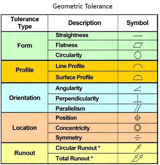
Form Tolerance
Form tolerance is related to the shape of a feature of a part. These are its types:
- Flatness
- Straightness
- Circularity
- Cylindricity
Form tolerance ensures that each feature exhibit correct geometric feature regardless of its location or how it is oriented. In this type of geometric tolerance, no datum axis is required to define.
Profile Tolerance
In this type of geometric tolerance, it is usually important to define a datum axis. This geometric tolerance controls:
- Profile of a Line
- Profile of a Surface
This type of geometric tolerance is responsible for ensuring that the shape, orientation, and location of the line or surface remain accurate with respect to ideal CAD-defined geometry.
Orientation Tolerance
Features like parallelism, perpendicularity, and angularity are specified to a certain angle with respect to the datum axis. This tolerance type controls the allowable deviation of a feature from that angle. In this type, it is mandatory to draw a datum axis first.
Location Tolerance
These tolerances are responsible for interchangeability, assembly, and functional alignment. In this type, the datum axis is mandatory to define. It has the following types:
- Position
- Concentricity
This geometric tolerance ensures the position of the features remains within the cylindrical tolerance zone with respect to the datum axis.
Runout Tolerance
This tolerance is used for those parts that rotate about an axis. This tolerance ensures that the part does not wobble when it rotates. Its types include:
- Circular Runout
- Total Runout
The datum axis is important to define in this type is also manadatory.
Why Is Geometric Tolerance Used?
In the past, traditional tolerances, which cover basic dimensions, such as length, width, and thickness of the part, were used, but the machining cost and material waste were higher. To cover these losses, geometric tolerances were developed.
To Meet Functional Requirements
Functional requirements include:
- How the part fits
- Distribution of the load within the part
- How it is located with reference to the datum axis
- Prevention of leak
- Control over the wear of the part
To meet these requirements, geometric tolerances are employed. For instance, tolerances in the flatness, parallelism, and perpendicularity help in uniform load distribution with the part.
To Ensure Reliable Assembly
After machining of the part, assembly is the second most important parameter that affects the performance and cycle of a component. Geometric tolerances ensure reliable assembly by efficiently controlling the orientation, location, and other features of the part with respect to the datum axis.
To Optimize Manufacturing Cost
In geometric tolerances, tight tolerances are applied only where the functionality is required, thereby preventing unnecessary machining. Single-pass machining is used instead of secondary operations, like honing, etc. These parameters lead to a reduction in manufacturing costs.
How to Use Geometric Tolerance
There is a proper process to apply geometric tolerances on a part, which starts with the identification of the functional requirements. Every step is briefly discussed below:
Identify Functional Requirements
Some functions are the core of the applications in which parts are employed. For instance, strength is the functional requirement of a shaft. It should transmit torque without yielding. So, the first step is to identify the functional requirements.
Select Right Geometric Tolerance Types
The second step is choose the geometric tolerance type (location tolerance, form tolerance, orientation tolerance, etc.). It is selected based on:
- Functional requirements
- Role of the part in assembly and motion
- Load path sensitivity
- Datum relationships
- manufacturability
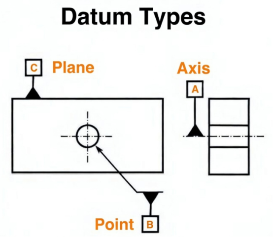
Define Datums
The third step is defining the datums in the geometry of the part. A single point or axis is selected around which all the features of the part are oriented in a cylindrical tolerance zone.
Apply Tolerances on Drawings
To apply geometric tolerances on a drawing, feature control frames (FCC) are used, which are further linked to functional datums. Then specify the permissible deviations in orientation, shape, etc., so that proper assembly, functionality, and manufacturing can be ensured.
Verify Tolerance when Assembly
For the verification of applied tolerances at the time of assembly, different tools, such as go/no-go gauges, dial indicators, plug gauges, and a coordinate measuring machine, are used.
How to Calculate Geometric Tolerance
Geometric tolerances can be related to form, orientation, or runouts. They are calculated through different formulas.
Calculate Form Tolerances
Form tolerances include flatness, straightness, circularity, and cylindricity.
- Flatness
Measures how much a surface deviates from a perfectly specified plane.
Formula: Flatness= Max height−Min height
- Straightness
How much a line deviates from a perfect straight line is called straightness.
Formula: Straightness= Max deviation from ideal straight line
- Circularity
Measures how much a feature, like a hole, deviates from a perfect circle.
Formula: Circularity= Rmax−Rmin
- Rmax is the maximum radius
- Rmin is the minimum radius
- Cylindricity
Measures how much a part is uniformly rounded, straight, and smooth along its axis.
Formula: Cylindricity= Rmax−Rmin
Calculate Orientation Tolerances
- Parallelism
Measures that a surface must not deviate from two parallel planes that are parallel to a specified datum.
Formula: Parallelism error= Max distance−Min distance
- Perpendicularity
Measures the deviation of an axis of a part from the cylindrical tolerance zone defined at 90° to a datum axis.
Formula: Perpendicularity error= Max deviation from 90°
- Angularity
Measures the deviation of an axis of a part from the cylindrical tolerance zone specified at a basic angle to a datum axis.
Formula: Angularity error= Max deviation from specified angle
Calculate Location Tolerances
- Position
Measures the deviation of an axis of a part from the 3D tolerance zone with respect to a datum reference.
Position= 2 × (x2+y2)1/2
- X2is the deviation in the x-axis
- Y2is the deviation in the y-axis
- Concentricity
Measures the alignment of all the median points of a part with the median points of a datum feature.
Concentricity= Max center deviation
- Symmetry
Measures the material distribution on both sides of the datum axis.
Symmetry= Max deviation of median plane
Calculate Runout Tolerances
- Circular Runout
Measures the variation of the surface element when the part is rotated at 360° about a datum axis.
Circular Runout= Max reading−Min reading
- Total Runout
Measures the deviation of a surface element of a part when it is rotated at 360° about a datum axis. It is checked through the entire surface.
Total Runout= Max reading−Min reading
Common Mistakes When Using Geometric Tolerance
Misunderstanding of geometric symbols, neglect of material condition modifiers, and functional requirements are the common mistakes people make when using geometric tolerances. These mistakes ultimately lead to reduced efficiency in the production and performance of the part.
Misunderstand Geometric Tolerance Symbols
It means when people understand the symbol of parallelism as perpendicularity and then machine accordingly. The misunderstanding of geometric tolerance symbols leads to poor functional properties, such as bearing wear improperly, and causes misalignment during the assembly.
Neglect Material Condition Modifiers
The neglect of material condition modifiers results in:
- Over-tight tolerances
- Loss of functional properties
- Higher inspection cost
- Assembly issues
- Increased scrap and rework
Neglect Functional Requirements
Neglect of functional requirements does not cause the inspection-related issues.
- Ultimately affects the part's performance.
- Part fails earlier during service
- Loss of performance
- Increased warranty and field failures
The Role of Geometric Tolerance in DFM & DFMA
The geometric tolerances can be applied in Design For Manufacturability (DFM) and Design For Manufacturability and Assembly (DFMA). They play their roles differently in both.
Geometric Tolerance in DFM
DFM is related to manufacturability and process capability. Geometric tolerances ensure that only necessary tolerances are applied consistently with respect to machining processes, such as machining, grinding, etc.
Geometric Tolerance in DFMA
In the case of DFMA, geometric tolerances also ensure the parts fit easily in assembly without any errors. So, they control the dimensional accuracy with respect to inspection, as well as assembly and functional requirements. While in DFM, geometric tolerances deal with only manufacturing-related tolerances.
How to Use Geometric Tolerance to Optimize Parts?
Through geometric tolerances, parts can be optimized for requirements, such as improved performance with lower material waste, easy machining, and lower costs.
Design Critical Features Properly
Critical features of a part are those features that directly affect the functional properties, assembly, and service life. For instance, the shaft axis is a critical feature in a bearing. In this case, GD&T focuses tolerances on functional geometry so that the part is manufactured with looser tolerances. GD&T helps to ensure easy assembly with reduced scrap and rework.
Control Manufacturing Process
Geometric tolerances control the manufacturing process by avoiding unnecessary tight tolerances in the part manufacturing. For instance, for a shaft in a bearing, only features, like straightness, surface finish, etc., are critical. So, geometric tolerances are only applied here, and manufacturing processes are selected accordingly.
Verify with Accurate Measurement
Geometric tolerances help in verifying the measurements because the dimensions are measured with respect to real-world applications. For instance, through geometric tolerance, not only are general dimensions measured in a shaft, but the total run-out with respect to a datum axis is measured.
Tips for Reading Geometric Tolerance Properly
A better understanding of geometric tolerances helps in manufacturing parts with higher efficiency, lower scrap and rework, and at lower prices. These are some tips to understand geometric tolerances effectively:
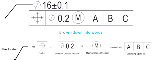
Understand FCF on Drawings
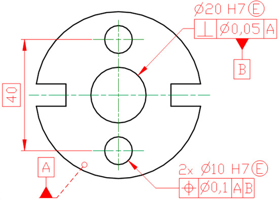
Every engineering drawing contains a Feature Control Framework. It contains the information about the required geometric tolerance and how to check it. It is an attached box to a feature. So, understand this framework completely and the meaning of each symbol, etc., before manufacturing or inspection. For instance, see the following figure:
Identify Symbols of Geometric Tolerance
Each geometric tolerance symbol refers to a different feature of a part. For instance, in the above figure, the symbol is for diameter. So, identify and understand each geometric tolerance symbol.
Understand Material Condition
Understanding of material condition means it should be known how a feature size affects the geometric tolerance and what to use in MMC, LMC, or RFS.
Conclusion
Geometric tolerances are the core of manufacturing any part. These tolerances ensure that the part fulfills all the functional and assembly-related requirements. These tolerances help achieve the higher precision at the cost-effective machining costs because of lower machining costs. Another reason for cost-effective machining is that the unnecessarily tight tolerances are removed from the drawing and machining of the parts. Geometric tolerances have five major types, i.e., form, orientation, run-out, profile, and location. Understanding of these tolerances results in higher productivity in a shorter time.
With decades of manufacturing experience, Tuofa precision CNC service can provide professional suggestions for your design of parts with deep understanding of geometric tolerance.
FAQ
What is the difference between dimensional tolerance and geometric tolerance?
Dimensional tolerance is related to the permissible variation in the size of the part. 0.2mm is a permissible variation in 20mm-long bolt. Geometric tolerance limits the variation in the part's orientation, location, shape, or runout, etc., of the part.
Is GD&T a CAD skill?
No, CAD is just a platform to communicate it. It is a skill in designing and manufacturing a part.
How to read geometric tolerances
- Identify the feature being controlled
- Read the tolerance value
- Check the datum axis
- Understand the tolerance zone
- Relate it to function
How to apply GD&T in drawings?
Follow these steps:
- Identification of functional feature
- Selection of the right tolerance type
- Defining of the datum axis
- Creation of feature control frame (FC)
- Attachment of tolerance to the correct feature
 Design for Manufacturing and Assembly: A Guide for Optimizing Parts