Tel/WeChat:
  Email:
 Home
HomeHow to Design Your Aluminum Casing for Electronic Devices?

 Published:Jun 05,2026
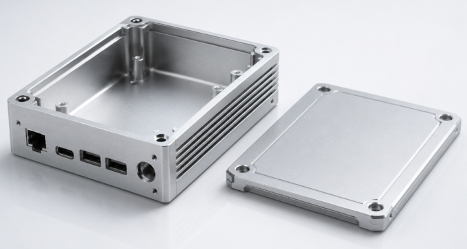
Designing an aluminum casing for electronic devices is not only about making a metal box look clean. A practical casing must protect internal electronic components, support internal components, allow connectors and buttons to work correctly, dissipate heat, and still be easy to machine. For a CNC machined aluminum enclosure, the design should be planned around both application requirements and manufacturing feasibility. This means the features you add should have a clear function, and the features you avoid should reduce machining difficulty, assembly risk, and production cost.
The following guide explains how to design your own aluminum casing while ensuring manufacturability. It focuses on design methods, design precautions, and available CNC machining methods for custom aluminum electronics enclosures.
Define the Application Requirements First
Before designing the shape of an aluminum electronics enclosure, start with the application. Different electronic devices need different casing features. A handheld controller, a power module, a sensor housing, and an outdoor communication box should not use the same design logic. The application decides the internal layout, external openings, wall thickness, heat path, sealing details, and mounting method.
Match Casing Features to Device Use
For a simple indoor device, the casing may only need internal support posts, connector cutouts, and a removable cover. For a power electronics casing, heat dissipation surfaces, thicker thermal contact areas, and possible heat sink fins become more important. For outdoor or industrial electronics, waterproof grooves, gasket compression areas, cable gland holes, and corrosion-resistant finishing should be considered early. This is why aluminum casing design should begin with function instead of appearance.
|
Application Need |
Typical Casing Feature |
CNC Design Focus |
|---|---|---|
|
Heat dissipation |
Thermal pads, thickened contact areas, fins |
Keep thermal surfaces flat and accessible |
|
Internal assembly |
Standoffs, bosses, screw holes, slots |
Avoid weak posts and leave tool clearance |
|
Waterproof use |
O-ring grooves, gasket surfaces, cable gland holes |
Control flatness and sealing compression |
|
External access |
USB, power, LED, display, button openings |
Add clearance, chamfers, and deburring |
Turn Requirements into CNC-Friendly Design Features
After the functional requirements are clear, the next step is to convert them into specific design features that can be machined reliably. For a custom CNC aluminum casing, every feature should have a purpose: holding internal components, transferring heat, sealing the enclosure, aligning connectors, or helping the product mount to another surface.
Design the Internal Layout Around Internal Components
When designing an aluminum casing for electronic devices, the internal components should be the starting point. The casing is not just an empty aluminum box. It should be designed around the parts inside it, including modules, connectors, batteries, displays, buttons, and cables. Before creating the outer shape, check these internal details first:
- Internal component size and position
- Internal mounting hole positions
- USB, Type-C, HDMI, or power connector locations
- Battery size and replacement space
- Display or LED indicator position
- Cable routing space
- Height of tall components
- Screw and fastener locations
This inside-out design approach helps avoid common assembly problems. For example, the port opening may not match the connector, the screw holes may interfere with electronic components, or the wires may be squeezed inside the casing. A good aluminum enclosure design should leave enough clearance between the internal components and the inner wall. It should also provide enough vertical space for taller components, wires, screws, and other parts.
Use Practical Wall Thickness and Corner Radii
For many CNC machined aluminum casings, a wall thickness of about 1.5-3.0 mm is a useful starting point. However, this number should not be treated as a fixed rule. The final wall thickness depends on the size, strength, sealing, and heat dissipation needs of the electronic device.
You may need thicker walls when the casing requires:
- Better structural strength
- Waterproof or dustproof sealing
- Threaded holes or screw bosses
- Heat dissipation areas
- Large flat surfaces
- Outdoor or industrial use
You may use thinner walls when the casing is:
- Small in size
- Used for lightweight electronic products
- Not exposed to heavy loads
- Designed only for indoor use
- Supported by enough internal structure
The inside corners of the casing should also have rounded corners instead of sharp corners. This is because CNC cutting tools are round, so they cannot make perfectly sharp internal corners. Adding a proper radius makes the part easier to machine, improves tool movement, and can reduce machining time.
Design Key Functional Features for Electronics Assembly
An aluminum electronic casing must be easy to assemble and safe to use. CNC machining allows accurate holes, pockets, bosses, and slots, but these details still need to be designed with enough clearance, strength, and accessibility. The goal is to make the enclosure protect the electronics without creating unnecessary assembly problems.
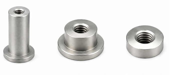
Mounting Standoffs, Bosses, and Threaded Holes
For CNC machined aluminum casings, mounting standoffs, bosses, and threaded holes should be designed with enough machining space and material strength. These features are small, but they directly affect machining difficulty and assembly reliability.
When designing these features, pay attention to:
- Keep enough wall thickness around threaded holes.
- Avoid placing screw holes too close to thin walls or edges.
- Make bosses large enough for stable machining.
- Leave enough thread depth for M2 or M3 screws.
- Avoid overly tall and thin bosses, because they may vibrate or deform during machining.
A practical boss and threaded hole design can reduce tool breakage, thread stripping, and assembly problems.
Connector, Button, and Display Openings
Openings are common features on CNC aluminum enclosures, but they can increase machining time if they are too small, too deep, or too close to other features. The opening size should include proper clearance for machining, surface finishing, and final assembly.
For CNC machining, it is better to:
- Avoid very narrow slots.
- Avoid sharp internal corners in rectangular openings.
- Keep enough distance between adjacent openings.
- Add small chamfers to opening edges.
- Avoid placing openings too close to the casing edge.
- Consider anodizing or coating thickness when the fit is tight.
These details help the cutting tool move more smoothly and reduce burrs around the openings.
Thermal and Sealing Features
Thermal and sealing features should also be designed with CNC machinability in mind. Heat dissipation areas, sealing grooves, and gasket surfaces often require accurate machining, so they should be simple, accessible, and easy to inspect.
For CNC aluminum casing design, focus on:
- Keep thermal contact surfaces flat and easy to machine.
- Avoid extremely thin heat fins if strength is required.
- Make O-ring grooves accessible to standard cutting tools.
- Keep gasket sealing surfaces continuous and flat.
- Avoid placing screw holes through the sealing path.
- Leave enough space around grooves for tool access.
These features can be machined well when the design is simple and tool-friendly. Overly complex grooves, narrow fins, or interrupted sealing surfaces may increase CNC machining difficulty and cost.
Avoid Features That Make CNC Machining Difficulty
Design precautions are just as important as design features. Many aluminum casing designs become expensive or difficult because they include shapes that are technically possible but not efficient to machine. Avoiding these features can improve CNC manufacturability, reduce tool wear, shorten lead time, and improve part consistency.
Common Features to Avoid
The following features should be avoided or redesigned when possible:
- Extremely deep pockets with narrow openings, because they require long tools and may cause vibration.
- Very thin walls, because they may deform during machining or finishing.
- Sharp internal corners, because CNC milling tools need internal radii.
- Unnecessary undercuts, because they may require special tools or extra setups.
- Overly tight tolerances on non-critical areas, because they increase inspection and machining cost.
- Threaded holes too close to edges, because they may weaken the casing or cause thread failure.
- Decorative complex surfaces without functional value, because they add machining time.
Control Tolerance Only Where It Matters
Not every surface of a CNC aluminum enclosure needs a tight tolerance. Critical areas include internal mounting positions, connector openings, sealing surfaces, threaded holes, and thermal contact areas. External decorative surfaces, large non-contact walls, and simple clearance pockets can often use general tolerances. This makes the design easier to machine while keeping the important functions accurate.
Select Aluminum Material and Surface Finish
Material and finish choices also affect the final design. Aluminum is popular for electronic enclosures because it is lightweight, corrosion-resistant, conductive, and suitable for CNC machining. However, different aluminum grades and surface treatments serve different applications.
Common Aluminum Materials for Casings
6061 aluminum is widely used for CNC machined aluminum enclosures because it provides good strength, machinability, and anodizing performance.
6063 aluminum is common for extruded aluminum enclosures with long, consistent profiles.
5052 aluminum is often used for sheet metal aluminum housings because it has good corrosion resistance and formability.
For a CNC casing with pockets, bosses, and precise cutouts, 6061 is often a practical choice.
Surface Finish Considerations
Anodizing, bead blasting, brushing, powder coating, and laser marking are common finishes for aluminum electronics casings.
Anodizing improves corrosion resistance and appearance, but it can affect electrical contact because anodized layers are not the same as bare conductive aluminum. If the enclosure requires EMI continuity or grounding, specify masked conductive areas before finishing.
Powder coating adds more thickness, so tight-fitting openings and threaded areas should be checked carefully.
Understand CNC Machining Methods for Aluminum Casings
Once the design is ready, the correct CNC machining method should be selected based on the enclosure shape, feature complexity, tolerance requirements, and production volume. CNC manufacturing can produce prototypes, low-volume aluminum casings, and precision enclosure components with consistent quality.
CNC Milling
CNC milling is the main process for custom aluminum electronics enclosures. It is used to machine:
- Outer casing shape
- Inner cavity
- Pockets and slots
- Screw bosses
- Connector openings
- Sealing grooves
- Chamfers
- Flat mounting surfaces
For simple box-shaped housings, 3-axis CNC milling is usually enough. For side holes, angled surfaces, or complex structures, 4-axis or 5-axis machining can reduce repeated clamping and improve accuracy.
CNC Drilling, Tapping, and Thread Milling
Most aluminum casings need accurate holes and threads. Common features include:
- Internal mounting holes
- Cover screw holes
- Threaded holes
- Counterbored holes
- Countersunk holes
- Cable gland holes
For small screws such as M2 or M3, leave enough material around the hole. Avoid placing holes too close to thin walls, edges, or narrow bosses. For deep or high-precision threads, thread milling is often better than tapping.
Secondary Operations and Inspection
After CNC machining, aluminum casings may need:
- Deburring
- Edge chamfering
- Anodizing
- Powder coating
- Laser engraving
- Cleaning
Key inspection points include:
- Hole position
- Thread quality
- Connector opening size
- Sealing surface flatness
- Surface roughness
- Final assembly fit
These steps help make sure the aluminum enclosure is ready for finishing and assembly.
Conclusion
A well-designed aluminum casing for electronic devices should connect design intent with CNC manufacturability. The best approach is to start with the application requirements, define the functional casing features, avoid difficult-to-machine details, choose suitable aluminum material and finish, and then confirm the proper CNC machining process. This helps the enclosure protect the electronics, support assembly, manage heat, and remain practical for production.
For custom aluminum electronics enclosure projects, a manufacturing partner should be able to review CAD files, identify machining risks, suggest DFM improvements, and produce prototypes or small-batch parts. Tuofa aluminum enclosure manufacturing can support CNC machined aluminum casings with precise pockets, threaded holes, connector cutouts, sealing surfaces, and surface finish requirements. This is useful when a design needs to move from an early CAD model to a functional aluminum housing for electronic devices.
 Efficient Part Design: Tips for Reducing Cost and Improving Parts Quality