Tel/WeChat:
  Email:
 Home
HomePerpendicularity in GD&T: Important Geometric Tolerance Symbol

 Published:Jan 29,2026
In drawing and manufacturing, GD&T(Geometric Dimensioning and Tolerancing) is mainly used. Multiple terms are used in a drawing to show different dimensions. Perpendicularity is one of these terms to verify if a dimension is close to 90°. This article focuses on perpendicularity and its related concepts.
What Is Perpendicularity In GD&T?
In GD&T, the orientation control is used to check how close a feature must be to 90° relative to a referenced datum, called perpendicularity. To be more specific, it controls whether an axis or a center plane is at 90° to a datum axis or plane or not. It doesn't control flatness or straightness.
Why Is Perpendicularity Important?
It is usually used in engineering design and manufacturing. It is an important feature in designing a part because it ensures:
- Proper assembly
- Structural stability
- Functionality of components
For instance, in engineering and manufacturing, this GD&T control checks if all the holes or pins are at 90° to a surface for proper assembly. Furthermore, it plays a crucial role in confirming whether structures, components, and systems are both functional and durable.
How to Understand Perpendicularity Symbol?
In designs and drawings of the parts, it is always mentioned through a symbol, like Ø, is always used to indicate the diameter. In general, symbols are used on the drawings instead of writing the word because it is a quick way to represent the type of dimension. Another example is chemical symbols, like Hf, which are used to represent a chemical element, i.e., Hafnium.
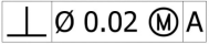
Perpendicularity Symbol
“⊥” is a perpendicularity symbol. The drawings of many parts, such as gear faces, bearing seats, brackets, etc., contain this symbol. This symbol is used where a 90° relationship is functionally critical.
Function of Datum
In GD&T, these are the functions of a datum:
- Establishes a fixed reference
- Ensures consistent orientation
- Defines the location of other features of a part
- Removes ambiguity during manufacturing and inspection
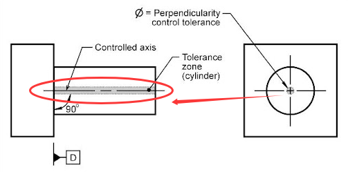
Tolerance Zone of Perpendicularity
A tolerance zone means a small zone that allows specified variation from a certain point. In the case of a tolerance zone of perpendicularity, it means the allowed variation from a perfect 90°.
Types of Perpendicularity Symbol in GD&T?
In GD&T, the symbol of perpendicularity can be applied in two ways, based on the respective requirement:
Axis Perpendicularity
The perpendicularity symbol is applied in an axis perpendicularity way for holes, pins, shafts, etc. It controls the orientation of an axis of a part with respect to a datum axis. For instance, in the above figure, it means: The axis of a hole must lie within the cylindrical tolerance zone of 0.02 mm, and that cylinder is oriented at 90° relative to the datum axis A.
Surface Perpendicularity
When it is a surface perpendicularity on a drawing, then it means the orientation of a flat surface relative to the datum axis. Its common applications include mounting faces, flange faces, etc.
Functions of Perpendicularity Symbol in Different Stages
The very first step in the manufacturing of a part is to make a drawing of that part. Now, that part can be a shaft or can be a screw, etc. So, on the drawings, multiple symbols are used to represent different dimensions. For instance, Ø is a symbol of diameter and ◎is a symbol of concentricity. In the same manner, perpendicularity is represented by ⊥. This section will help you to learn the functions of perpendicularity at different stages of your projects.
Engineering Drawings
To understand the meaning or use of perpendicularity in engineering drawings, please see the following drawing:
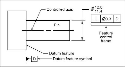
Overall, in this drawing, the following features are mentioned:
- Ø: For diameter
- Controlled axis
- ⊥: For perpendicularity
- A datum axis
In this drawing (GD&T), there is a pin axis relative to datum D, for which this drawing specifies ⊥.
Here, datum D is the primary reference plane. Please see the flat face on the left in the drawing.
In this drawing, ⟂| ⌀0.3 | D, is a feature control frame, which means:
- The pin axis must be perpendicular to datum axis D
- ⟂| ⌀3 | D means a tolerance zone of 0.3 mm. So, the axis must be within this cylindrical reference zone.
- This tolerance zone is oriented at 90° with respect to datum D.
CNC Machining
Suppose a rectangular block is under CNC machining:
- The bottom face will be defined as datum A
- A vertical hole is drilled from the top face
So, the perpendicularity tolerance will be applied to the hole axis with respect to datum A.
In simple words, it means that the axis of the hole must be perfectly vertical (at 90°) with respect to the bottom face and within the stated tolerance.
Perpendicularity ensures in CNC machining that the hole remains perfectly at 90° relative to the bottom face. If the drill slightly tilts, the part will be considered out of tolerance.
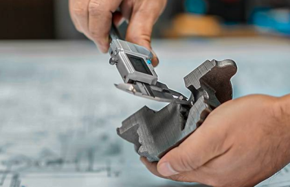
Quality Inspection
The purpose of quality inspection with respect to perpendicularity is to inspect how close a feature is to true 90° with respect to its datum and within the specified tolerance zone. It is inspected:
- Using a Coordinate Measuring Machine (CMM)
- Using surface plate + Dial Indicator
- Precision Square
- Gauge Pin + Dial Indicator
How to Measure Perpendicularity in GD&T?
In GD&T, ISO 1101 and ASME Y14.5 standards are used to measure the perpendicularity using different tools, such as a coordinate measuring machine (CMM).
Coordinate Measuring Machine (CMM)
The steps to evaluate perpendicularity using a coordinate measuring machine are given below:
- Establish the datum
- Measure the controlled feature through a CMM probe
- Construct the ideal perpendicular axis
- Calculate the deviation
The formula to measure the perpendicularity axis is:
Perpendicularity=2×dmax
dmax= maximum distance between the actual axis and the ideal perpendicular axis
While for surface perpendicularity, this formula is used:
Perpendicularity=max(ΔZ)−min(ΔZ)
ΔZ indicates the deviation of surface points from the ideal perpendicularity axis.
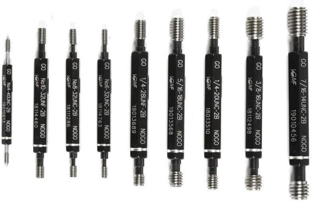
No-Go Gauges
No-Go gauges are used to check whether the feature axis is within the cylindrical tolerance zone or not. In simple words:
If a part fits the No-Go gauges à fail
If a part does not fit the No-Go gauges àpass
Perpendicularity vs Other GD&T Symbols
As mentioned earlier, in a drawing, there are multiple symbols used at a time that indicate different meanings. These symbols can be for a diameter or an angle. That's why it is important to understand how these symbols are different from perpendicularity.
Perpendicularity vs Parallelism
The common example of parallelism can be found in rail tracks, where each side must be at 0° with respect to the other. So, the major difference between perpendicularity and parallelism is of angle, i.e., 90° vs 0°.
|
Aspect |
Perpendicularity ⟂ |
Parallelism ∥ |
|---|---|---|
|
What it controls |
90° orientation between features |
Same-direction orientation between features |
|
Angle requirement |
Exactly at right angle (90°) |
0° difference (never meets or diverges) |
|
Typical example |
Pin axis ⟂mounting face |
Shaft axis ∥guide rail |
|
Tolerance zone |
Two parallel planes or a cylinder at 90° to datum |
Two parallel planes or a cylinder aligned to datum |
Perpendicularity vs Angularity
Angularity simply means to control the angle. Compared to perpendicularity which focuses only on 90°, angularity checks if the part is perfectly oriented at the specified angle.
|
Aspect |
Perpendicularity ⟂ |
Angularity ∠ |
|---|---|---|
|
What it controls |
90° orientation between features |
Fixed angle other than 90° |
|
Angle value |
Always exactly 90° |
Any specified angle (e.g., 30°, 45°) |
|
Typical example |
Pin ⟂ mounting face |
Chamfer or angled hole |
|
Tolerance zone |
Planes or cylinders at 90° to datum |
Planes or cylinder at specified angle |
Perpendicularity vs Position
Where perpendicularity focuses only on whether a feature is perfectly oriented at a perfect 90° to the datum, position controls if the features are located from the datums (X, Y, Z).
|
Aspect |
Perpendicularity ⟂ |
Position ⌖ |
|---|---|---|
|
What it controls |
Orientation only |
Location andorientation |
|
Relation to datum |
Must be 90° to datum |
Located from datums (X, Y, Z) |
|
Typical example |
Pin ⟂base face |
Hole located in a bolt pattern |
|
Tolerance zone |
Planes or cylinder at 90° |
Cylindrical (or rectangular) zone at true location |
Flatness vs Perpendicularity
The major difference between perpendicularity and flatnessis:
Flatness checks whether there is any surface distortion, such as whether it is truly flat or not. While perpendicularity checks if one feature is perpendicular to another or not.
|
Basis |
Flatness |
Perpendicularity |
|---|---|---|
|
What it checks |
Whether the surface is truly flat |
Whether a feature is perpendicular to another |
|
Datum needed |
No |
Yes |
|
Main concern |
Surface distortion (bow, waviness) |
90° alignment to a reference |
|
Simple example |
Machined base plate |
Hole or face square to base |
Importance of Perpendicularity in CNC Machining
Every geometric term is important in GD&T and CNC machining because it ultimately affects the efficiency of that workpiece. Perpendicularity is important when the alignment of a feature with respect to a datum axis is important. The following points show its importance in CNC machining:
Ensure Precision of Parts
Perpendicularity in GD&T and during CNC machining ensures precision of parts by providing:
- Accurate assembly
- Functional reliability
- Interchangeability
- Uniform load distribution
- Reduced rework and scrap
In engineering terms, it ensures the precision of a part by making sure that the part's feature remains exactly at 90° relative to the datum axis.
Improve Quality Consistency
During CNC machining, when every part is manufactured by making sure that the part's feature remains exactly at 90° relative to the datum axis, it improves quality consistency. This consistency comes due to:
- Common reference
- Repeated machining results
- Predictable functional behaviour
- Stable inspection criteria
- Reduced variation in the assembly
Ensure Proper Assembly
When machining follows perpendicularity properly, it results in proper assembly because of misalignment between mating features. Furthmore perpendicularity ensures perfect assembly due to:
- Accurate fastener alignment
- Correct mating of parts
- Maintained clearances
- Stack-up control
Challenges in Controlling Perpendicularity During Machining
During CNC machining, multiple challenges can arise. These issues can be due to incompatible tools with respect to the material or location of the part, etc. These are some issues:
Tool Limitations
Due to issues, such as difficult design, wear, stiffness, or accuracy limits, the cutting tool itself cannot achieve a perfect 90° alignment. That results in the deflection of tools and low machining accuracy.
Machining Sequence Effect
During machining the parts, another issue is the sequence of machining processes. For instance, if a reference face is machined at the earlier stage but can be distorted due to later heavy cuts. So, the perpendicularity is lost.
Material Deformation
In case of thin or long parts or due to clamping pressure distorting the workpiece, it results in the loss of perpendicularity.
Tips for Using Perpendicularity in GD&T
There are some factors that affect the usage of perpendicularity in GD&T. If these factors are understood well, they help in achieving the perpendicularity and hence the machining results. Designers can read these tips for optimizing the engineering drawings, and the engineers or manufacturers can improve the quality of parts with this guide.
Always Define A Datum
When a drawing of a part is made, the very first step should be to define a datum axis because this is the standard reference point around which other features of a part are oriented.
Control Orientation
Control orientation in GD&T, it ensures that an axis is exactly 90° relative to a datum axis.
- It reduces cumulative angular errors introduced during machining setups
- Allows machinists to focus on maintaining squareness rather than chasing tight tolerances
Determine Reasonable Tolerances
If the reasonable tolerances are determined earlier, they:
- Prevent over-tight perpendicularity tolerances
- Ensure the tolerances match the function of the part
- Avoid false precision where extreme accuracy adds no functional benefit
Conclusion
Perpendicularity is an important feature in GD&T that ensures that all the features of a part remain at 90° to a datum axis. It is represented by ⊥ a symbol. It improves the functionality of a part by accurate load distribution, alignment, and wear, etc. It is measured using tools, such as a coordinate measuring machine (CMM). If there is an error in achieving perpendicularity, it will cause issues in assembling the parts.
Tuofa CNC manufacturer can provide professional recommendations for prototyping your parts. We offer DFM analysis before your parts are manufactured, in this way, your parts can perform their functions well.
FAQ
What is GD&T?
Geometric Dimensioning and Tolerancing (GD&T) is used in manufacturing to fix dimensions and tolerances for the parts on the drawings.
What is GD&T used for?
It is used in:
- Engineering drawings
- Mass production
- Automotive industry
- High-precision machining
- Inspection and quality control
What is the difference between tolerance and GD&T?
Tolerance means the permissible variation in the dimensions of a part, while GD&T controls geometry.
 Geometric Tolerance: What, Why and How to Use?