Tel/WeChat:
  Email:
 Home
HomeWhat Is ISO 286? Understanding Hole & Shaft Tolerance

 Published:Mar 06,2026
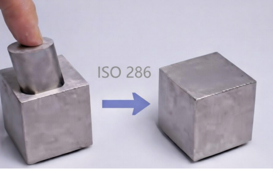
Numerous cylindrical mating parts are being manufactured around the world. A truly universal approach would be that two standardized components must fit properly. It should not matter where it was manufactured. If all factories agree on a single universal framework for dimensional tolerances, it can bring about this universal approach. ISO 286 is one such endeavor. It is now adopted by a vast majority of manufacturers around the world. It governs limits, fits, and tolerances. Let's take a deep insight into this topic.
What Does ISO 286 Mean?
The International Organization for Standardization (ISO) has formulated the ISO 286 standard for defining limits, tolerances, and fits. This standard is accepted globally. It defines deviation limits. This ISO system of limits and fits is specifically for shafts and holes. Compliance with ISO 286 ensures that part dimensions become supplier-independent. It means that no matter where the part is produced, it'll mate accurately. Hence, ISO 286 ensures a predictable fit during assembly.

Development of ISO 286
Before the development of ISO 286, there were several national standards. The Brits had BS, while the Germans had DIN and so on. As international trade became more common, a need for a single tolerance standard was felt. ISO unified the various national standards into a single ISO tolerance system. These harmonized tolerancing rules gave more clarity to designers and clients internationally.

Structure of ISO 286
- ISO 286-1
In simple terms, ISO 286-1 is the theoretical portion of the ISO 286 standard. It provides a theoretical and mathematical basis for setting up the ISO system of limits and fits. It tells how IT grades are determined and how fits are defined. It gives formulae for calculating tolerances. ISO 286 defines fundamental deviations and letters.
- ISO 286-2
In contrast to ISO 286- 1, ISO 286 -2 is the practical portion of the ISO 286 standard. It gives data tables and numerical limit values. Instead of new calculations each time, designers can refer to the tabulated data for referencing limits, tolerances, and fits.
Key Elements of ISO 286 System
ISO 286 draws out a structured approach to calculate limits, fits, and tolerances. It uses linear dimensions, which are then subjected to calculations based on fundamental deviations and IT grades. Compliance with the ISO 286 standard ensures that parts remain functional within acceptable tolerance limits.
Linear Dimensions
ISO 286 standard uses nominal sizes in millimeters. The ISO system of limits and fits is then applied to these nominal sizes. Let's say the diameter of a shaft is expressed in millimeters as 50mm. All calculations are then made relative this 50mm diameter when referring to the shaft.
Fundamental Deviation
Fundamental deviations in ISO 286 are designated by letters. Uppercase letters are used for holes. Lowercase letters are used for shafts. Letter ‘H' means that the lower limit for deviation is zero for holes. Similarly, letter ‘h' means that the upper limit for deviation is 0 for shafts. Other letters deviate above or below zero. The chart below shows the notation of some of the elements.
|
Symbol |
Part |
Zone Position |
Typical Fit |
|---|---|---|---|
|
H |
Hole |
lower deviation = 0 |
Hole -basis system |
|
h |
Shaft |
upper deviation = 0 |
Shaft-basis system |
|
g |
Shaft |
Below nominal |
Clearance |
|
f |
Shaft |
Further below nominal |
Larger clearance |
|
k |
Shaft |
Slightly above nominal |
Transition |
|
m |
Shaft |
More above nominal |
Tight transition |
|
p |
Shaft |
Above nominal |
Interference |
|
JS |
Hole/ Shaft |
Symmetrical about nominal |
Centered precision fit |
IT Grades
IT grades are abbreviated for ‘International Tolerance Grades'. IT is suffixed by a number from 01 to 18. The smaller the number, the narrower the tolerance. The chart below shows where each IT grade is used.
|
IT Grade |
Precision Level |
Tolerance range |
Applications |
|---|---|---|---|
|
IT01-IT4 |
Ultra precise |
Extremely small variation |
Measuring gauges and precision instruments |
|
IT5-IT6 |
Very high precision |
Very tight tolerance |
Bearing seats, high-speed shafts |
|
IT7-IT8 |
High to medium precision |
Tight tolerance |
CNC machined parts and gear fits |
|
IT9 - IT11 |
Medium Precision |
Moderate tolerance |
Standard mechanical components |
|
IT12 -IT14 |
Low precision |
Wide tolerance |
Fabricated and welded parts |
|
IT15-IT18 |
Very low precision |
Very wide tolerance |
Rough machining |
Limits and Fits System
The ISO system of limits and fits indicates how two mating parts will assemble. Would there be a clearance fit or an interference fit? What would be its magnitude?
Hole & Shaft Tolerance
As an example, H7/h6 means that the lower limit of deviation for the hole and the upper limit of deviation for the shaft are zero. The numbers 7 and 6 are used to calculate tolerance limits.
Types of Fits Defined by ISO 286
ISO 286 defines three basic types of fits:
- Clearance fit: There is always a space between the hole and the shaft. The volume of space depends on nominal dimensions and IT grades.
- Interference fit: The diameter of the hole is smaller than the shaft. Thermal methods might be needed to achieve an interference fit.
- Transition fit: It comes between inference fit and clearance fit.
Tolerance
Tolerance is actually the acceptable deviation from the nominal dimensions. IT grades control it. Tight tolerances give very precise dimensions but increase machining costs. On the contrary, wider tolerances increase productivity and reduce machining cost.
ISO 286 vs Other Tolerance Standards
As international trade is common now, an equivalence for standards might be needed. In this regard, ISO 286 is sometimes compared with other dimensional and geometrical standards. Each standard serves its own function. Compliance with a particular standard is a matter of mutual agreement between the buyer and the seller. The table gives an overview of some common standards:
|
System |
Standard |
Primary Focus |
Controls |
|---|---|---|---|
|
ISO Limits and Fits |
ISO 286 |
Limits and fits |
Hole and shaft tolerances, IT grades |
|
GD& T |
ASME Y14.5 and ISO 1101 |
Geometric dimensioning |
Form, orientation, location and runout |
|
General Tolerances |
ISO 2768 |
Default Tolerances |
Unspecified linear and angular dimensions |
|
ASME |
ASME B4 . 1 |
Fit classification |
Running, locational and force fits |
|
DIN |
DIN 7154 |
Limits & fits |
Linear size tolerances |
|
JIS |
JIS B 0401 |
Limits and fits |
Linear size tolerances |
Differences between ISO 286 and GD&T
While ISO 286 primarily focuses on fits during assembly, GD&T controls both dimensions and location. GD&T requires size, form, orientation, location, and runout to be defined. GD&T is also concerned about flatness, concentricity, perpendicularity, and position. It is governed by ASME Y14.5 and ISO 1101.
ISO 286 vs ISO 2768
ISO 286 is specific to holes and shafts. But ISO 2768 is a general tolerance standard. It classifies tolerances in broad classes like fine, medium, and coarse. It is commonly used for non-critical dimensions.
ISO 286 vs ASME
While ISO 286 is an international standard. ASME is limited to the North American industry only. Just as ISO 286 expresses deviation and IT grade in letters+ numbers like h6 etc., ASME B4.1 gives class-based fits. Common classes include RC, LC, and FN. ISO 286 requires linear dimensions to be given in ‘mm'. On the other hand, ASME allows both imperial and metric units.
ISO 286 vs DIN
Before the advent of ISO 286, Germany adopted DIN 7154. But now, it is almost completely harmonized with ISO. It has a very similar structure to ISO 286.
ISO 286 vs JIS
Similarly, Japan also harmonized its dimensional tolerancing standard with ISO 286. JIS B 0401 is very similar to ISO 286.
How to Use ISO 286?
A sequential workflow can be adopted to implement the ISO 286 standard. Each step comes in its own place. Starting from the determination of basic size, followed by the selection of fit type, the workflow ends with ensuring that dimensions are accurately achieved. Here is a brief explanation of this workflow.
Determine Basic Size
The foremost step is to determine a basic size. All deviations and tolerances are calculated relative to this basic size. As an example, if 40mm is determined as the nominal diameter of the shaft, all calculations would be made according to this 40mm.
Select Fit Type
As already discussed, ISO 286 specifies three fit types:
- Clearance fit
- Transition fit
- Interference fit
Selection of the suitable fit type will help move to the next step.
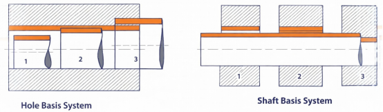
Choose Hole or Shaft Basis
A choice between hole basis and shaft basis exists. In hole basis, the tolerance of the hole is fixed as H. Shaft tolerance varies. Converse is true for the shaft basis. The table below highlights preferred fits according to ISO 286 standard:
|
Fit Type |
Hole-Basis Example |
Shaft-Basis Example |
Typical Application |
|---|---|---|---|
|
Clearance |
H7/g6 |
G7/h6 |
Sliding or rotating parts |
|
Light clearance |
H7/h6 |
H7/h6 |
Accurate sliding fit |
|
Transition |
H7 / k6 |
K7/h6 |
Precise Positioning |
|
Tight transition |
H7/m6 |
M7/h6 |
Accurate mounting |
|
Interference |
H7/p6 |
P7 / h6 |
Press - fit assemblies |
|
Heavy Interference |
H7/s6 |
S7/h6 |
Permanent joints |
Select Tolerance Grade
Tolerance grade determines the level of tolerance. It is notated in IT numbers. The smaller the number, the tighter the tolerance. The table below shows IT grades and their common usage:
|
IT Grade |
Precision Level |
Typical Manufacturing Process |
|---|---|---|
|
IT01-IT4 |
Ultra precision |
Gauging, lapping, super-finishing |
|
IT5-IT6 |
Very high precision |
Grinding, precision CNC machining |
|
IT7-IT8 |
High Precision |
Standard CNC machining and reaming |
|
IT9 -IT11 |
Medium precision |
Drilling and milling |
|
IT12- IT14 |
Low precision |
General machining and fabrication |
|
IT15-IT18 |
Very low precision |
Casting or rough machining |
Mark on Engineering Drawing
Once all details are determined, they need to be marked on the engineering drawings. ISO 286 specifies a format as follows:
Basic Size + Hole Symbol / Shaft Symbol
As an example, 40mm H7 /h7 gives the nominal size, followed by hole tolerance and shaft tolerance, respectively.
Guide Machining
Machining depends on the tolerance level. Tighter tolerances require a stringent control. As an example, IT4 tolerance may require a controlled temperature environment and fine grinding. While IT 12 might not need any additional controls. It all depends on tolerances.
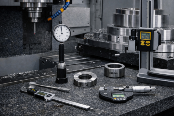
Inspect Part Dimensions
After the final part is manufactured, dimensions should be verified in a trial batch as well as in samples in subsequent mass production. Tools like vernier calipers and screw gauges are used for this purpose. For more precise results, CMM can be used.
Applying ISO 286 Tolerance Standard in Various Industries
The application of ISO 286 in the manufacturing of components provides an agreed-upon framework for maintaining tolerances. It not only does that but also ensures universal interchangeability of parts. All high-end industries like aerospace, medical, mechanical, and automotive take advantage of ISO 286 in manufacturing.
Aerospace Components
Aerospace components have a very tight QC for flight safety and operational reliability. Components that are subject to high loads require interference fits. Proper fitting of rotating components requires good concentricity. All parts must endure vibration and overheating. Commonly, components such as turbine shafts, bearing housings, actuator cylinders, landing gear bushings, and structural coupling sleeves are in compliance with ISO 286.
Automotive Parts
Many automotive parts are subjected to rotational movement and torque transmission. Rotating parts require a clearance fit for rotating shafts. Interference fits in torque-transmission parts are required to prevent slipping. Adoption of ISO 286 standards maintains global interchangeability of parts.
Mechanical Structural Parts
Mechanical parts are designed while considering load transfer efficiency and alignment. Less than optimum fitting can result in wear or misalignment. Common mechanical parts include machine frames, industrial rollers, hydraulic cylinder components, couplings, flanges, and heavy equipment bushings.
Precision Medical Parts
Medical parts require an ultra-high level of precision. This micro-level dimensional consistency can be maintained by adopting IT5-IT6 or finer tolerances. As medical implants need operation of the human body, there is no margin of error. Parts like surgical instrument joints, orthopedic implant connectors, prosthetic components, and dental tool shafts must pass a stringent QA before operation. Adoption of ISO 286 supports this quality assurance.
Common Mistakes When Using ISO 286
People often make some mistake commonly when implementing ISO 286. While these are often small mistakes, they create huge consequences. So, manufacturers must be mindful of these common mistakes
Confuse Hole Basis & Shaft Basis
Confusing the hole-basis system with the shaft-basis system is a very common mistake. Mostly hole basis is adopted in designs. It is so because drill bits, reamers, and other hole-making tools are standardized. So, it makes sense to take the deviation for the hole as zero. If the hole basis is confused with the shaft basis, then it'll create problems in manufacturing and assembly. Improper fitting will render components useless.
Select Inappropriate IT Grades
Adoption of a reasonable IT grade is necessary. Tight tolerance grades like IT 5 or finer incur extra costs in manufacturing. If non-critical components are allocated tight tolerance grades, then it'll make them exceptionally costly. On the other hand, loose tolerances like IT11 might not be suitable for aerospace applications where flight safety is the foremost goal.
Ignore Max & Min Limits
Ignoring the limits of tolerance can make unintended fit. For example, in a component where a clearance fit is required, if the hole is made slightly tighter and the shaft a bit wider, then it might result in an unintended interference fit.
Tips for Using ISO 286 in Part Designs
Here are some tips devised for proper application of ISO 286 in parts designs.
Choose the Fit Based on Function
Fit selection must be made depending on the function. Service conditions such as type of motion, load transfer, and alignment accuracy must be evaluated. It then decides whether a clearance or transition of interference fit is required.
Avoid Over-Tight Tolerances
Maintaining tighter tolerances is costly. They must be mandated when necessary. Otherwise, there can be a loss of productivity and finances.
Proper IT Grade Selection
Each industry has its own selection of IT grades depending on the cruciality of functions. On one hand, a simple structural component might suffice with an IT11 or higher. On the other hand, a medical implant might require IT5 or a finer grade. It depends on functionality.
Combine ISO 286 with GD&T When Needed
ISO 286 only controls the linear dimensions. But when it comes to positioning, GD&T is required. Positioning criteria like concentricity, perpendicularity, parallelism, etc., can be ensured by combining ISO 286 with GD&T.ISO 286 only controls the linear dimensions. But when it comes to positioning, GD&T is required. Positioning criteria like concentricity, perpendicularity, parallelism, etc., can be ensured by combining ISO 286 with GD&T.
Applying ISO 286 in CNC Machining
The application of ISO 286 helps to maintain dimensional consistency in CNC-machined parts. It enables the determination of machining strategy, tool selection, finishing processes, and inspection methods.
Typical IT Grades in Machining Processes
|
IT Grade |
Precision Level |
Typical Manufacturing Process |
|---|---|---|
|
IT01-IT4 |
Ultra precision |
lapping, super-finishing |
|
IT5-IT6 |
Very high precision |
precision CNC machining |
|
IT7-IT8 |
High Precision |
Standard CNC machining and reaming |
|
IT9 -IT11 |
Medium precision |
Drilling and milling |
|
IT12- IT14 |
Low precision |
General machining and fabrication |
|
IT15-IT18 |
Very low precision |
Casting or rough machining |
Using IT Grades to Guide Process Selection
IT9 or above grades are usually achievable with standard milling operations. IT7-IT8 may be achieved with some good calibration of tools. But, IT6 or finer grades require additional processing like grinding, honing, etc.
Verifying Tolerances of CNC Parts
Dimensions of the CNC-machined parts must fall between the upper and lower limits of tolerance. In many conditions, a vernier caliper can accurately check the dimensions. But, for a more precise control, micrometer screw gauges or dial bore gauges may be employed. CMM might be used for very tight tolerance requirements.
ISO 286 and Surface Treatment
Surface treatment processes modify the surface in ways that affect dimensions. There can be an increase or a decrease depending on the processing. Surface roughness (Ra) values also change. So there can be a need to validate products by including requirements of surface finish standards, like ISO 4278 alongside ISO 286.
Surface Finish for Tolerances
Low IT grades require smoother surfaces to fit properly. Rough surfaces have microscopic peaks and valleys. This surface topography can give inaccuracy in readings and create unintended fit conditions. So, finer IT grades should have a smooth ground surface.
Impact on Secondary Surface Processes
Some secondary treatment processes, like electroplating and anodization adds thickness to the final part. While other processes like lapping or polishing reduce the size. So, if the parts are to be subjected to secondary treatment, then the consequent dimensional changes must be accounted for.
Conclusion
ISO 286 is now a universally accepted standard for limits, fits, and tolerances. Its main scope of implementation is for cylindrical mating parts. Since its inception, many national standards like DIN and JIS have harmonized with it. Adoption of ISO 286 gives clarity to designers, manufacturers, and assembly teams.
Tuofa 5-axis custom service helps you machine parts with high precision based on desired tolerance so that the machined parts can match other parts.
FAQ
What is the ISO for linear dimensions?
ISO 286 is the standard formulated by ISO for linear dimensions.
What is the ISO 2768 standard?
ISO 2786 is the standard for general tolerancing rules for linear and geometrical dimensions on engineering drawings when there is no specific tolerance indicated individually.
What is the standard tolerance for CNC machining?
Generally, CNC machining without any additional processing produces IT7-IT8 grades. It is roughly equivalent to ±0.01-0.05 mm.
 On Demand Manufacturing: On Demand Machining and Process