Tel/WeChat:
  Email:
 Home
HomeScotch Yoke Mechanism: How It Works, Design, and Machining Tips

 Published:May 14,2026
Wide choices of mechanism are available for motion control elements. Elegant and reliable solutions can result from old and ‘primitive’ mechanisms. Among the earliest of such machines is the Scotch yoke mechanism. This is a small-footprint machine element that is used to convert rotary motion into high-precision linear motion. It has little or no backlash and a resilient, low part-count mechanism.
This deep-dive guide introduces you to how the Scotch Yoke, or slotted link mechanism works, and how to specify and size it. It also provides practical solutions to manufacture reliable parts, by using Tuofa as your outsourcing supplier.
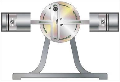
A scotch yoke mechanism schematic
What Is Scotch Yoke Mechanism
This mechanism's origin is unknown, but it's so widely used that it's considered obvious. It appeared in many very early pumps, steam valve gear, saws, and powered looms. It delivered simple solutions, despite a reputation for poor resistance to side loads and wear, in some uses.
What Is Scotch Yoke
The Scotch yoke uses a slotted link driven by an eccentric crank-pin, to convert rotary into linear motion. The crank-pin slides inside the slot, alternating the direction of force applied.
The result at the linear output is simple-harmonic motion (SHM), as the displacement varies following a sine wave.
In raw terms, output has:
- smooth acceleration throughout the stroke
- highest force at mid stroke
- zero velocity at stroke ends
- symmetric motion profile
There are comparable mechanisms, with various characteristic strengths and weaknesses. The slider-crank suffers distorted harmonic motion. The Watt linkage motion depends heavily on small changes in linkage design. The Scotch yoke serves when precision of force/motion and simplicity are paramount.
Why Engineers Still Use It
Scotch yokes mechanisms are typical in valve actuators, automation, and material/scintific test rigs. They deliver:
- Lower part-count than alternatives
- Direct conversion of motion at a point-of-action, without intermediate joints
- A compact envelope, delivering linear output
This facilitates lower BOM complexity and easier sourcing.
How the Scotch Yoke Mechanism Works
Once seen in operation, the mechanism-kinematics of the Scotch Yoke requires little explanation. However, the obvious motion entails functional detail that deserves closer analysis.
What Moves, What Stays Fixed
In a slotted link mechanism:
- The crank rotary motion is most often the input of motion/force
- The eccentric pin follows a circular path
- The pin experiences a moving point, sliding contact with the yoke, cycling through a full rotation
- The output is linear motion
- The frame/guide constraining the slider remains fixed
The dominant force interaction occurs at the pin-slot interface point. The crank-pin rotary motion pushes the yoke back and forth in precise simple harmonic motion.
How Rotation Turns Into Linear Motion
The pin pushes against the slot walls, on alternating sides of the slot. As the crank rotates:
- At the system-defined 0°, the yoke sits at mid-position, the pin at the slot-end, applied force momentarily at zero
- At 90°, the pin sits at slot-center, the slider at full displacement and the force at maximum
- At 180°, the pin returns to slot-center
- At 270°, the pin reaches the opposite end of the slot, peak force reversed
This produces pure harmonic motion, unlike slider-crank systems that distort motion near endpoints. Only a non-lobed (circular) cam-follower offers comparable SHM and simplicity.
Parts of a Scotch Yoke Mechanism
The part count of the Scotch yoke mechanism is low, and the parts robust and simple to manufacture.
Crank and Pin
The pin's eccentric radius defines the stroke. The pin transfers force into the slot. The design and execution must focus on:
- hardened pin surfaces, to resist the high wear, in angular-contact sliding
- tight pin concentricity ( ≤01 mm) ensures precision of motion
- smooth pin finish (8 µm) to prevent galling and uneven friction
Yoke and Slot
The slot translates the crank motion and transfers load. Slot-to-pin contact areas are the high wear-risk.
Critical parameters:
- slot width tolerance target: ± 0.01to 0.02 mm
- straightness: 02 mm/100 mm
- surface hardness (steel): > 50 HRC
Guides and Frame
Guide bearings maintain slider alignment and resist the inherent side forces. Poor alignment increases side load/wear.
Design and manufacturing targets:
- parallelism: 01 mmor better
- high rigidity, to prevent deflection and alignment-loss under load
Bearings, Bushings, and Lubrication Points
These control/moderate friction and extend device life.
Options to consider:
- bronze bushings are cost-effective and resist wear, but are unsuitable for high-force systems
- needle roller bearings are best for high load applications
- PTFE-lined surfaces offer a low maintenance solution in low force mechanisms
As in all mechanical systems, poor materials selection and lubrication failure are the common causes of wear.
Scotch Yoke Motion Calculations
The mathematics that govern Scotch yoke system motion are not complex. However, you must give due consideration to the demands and limits that apply. Otherwise your outcome may be unsatisfactory in performance or wear.
Stroke and Speed Limits
Calculation of the Scotch yoke mechanism performance is clearly defined by the Engineers Edge
Stroke results from crank radius:
- Stroke = 2 x r
Where r = the crank radius
The speed limit depends on:
- material strength
- lubrication
- allowable wear rate
Typical applications run below 600 RPM - often much slower - to control heat and wear.
Acceleration and Peak Loads
Acceleration follows sinusoidal motion:
- Peak acceleration ∝ ω²r
Where:
- ω= angular velocity of the rotation input
Thus, load rises sharply with speed, under a square-law relationship.
Side Load on the Slot and Guides
Side force relates to friction and the angular position of the crank.
- Side load peaks near mid-stroke
- This determines slot wear and guide friction
Wear can be moderated by increasing the slot width to accommodate hardened inserts.
Torque Ripple and Drive Sizing
Torque demand is not steady.
- High torque occurs near stroke-ends
- Torque reaches zero at mid-stroke
Drive motor sizing must allow for peak demand, rather than average load. Underpowering leads to stalling, vibration, and overheating.
Scotch Yoke vs Slider-Crank: Main Differences
There are various solutions to the rotary-to-linear conversion of motion. The differences are subtle in some respects. Each option offers some relative advantages, depending upon the context. These relative advantages (and issues) narrow the selection process.
Motion Profile
|
Feature |
Scotch Yoke |
Slider-Crank |
|
Motion type |
Pure harmonic |
Distorted harmonic |
|
Velocity curve |
Smooth |
Uneven |
|
Accuracy |
Higher |
Lower |
Acceleration and displacement differences between the Scotch yoke and slider crank are shown here
Force and Side-Load
|
Factor |
Scotch Yoke |
Slider-Crank |
|
Side load |
Higher |
Lower |
|
Contact stress |
Concentrated |
Distributed |
|
Wear rate |
Faster |
Reduced |
Wear and Maintenance
Scotch yoke systems can experience accelerated wear, as discussed by the ASME. The sliding contact is challenging for many bearing-material pairs. This shows most in pin wear, as abrasion is more localised on the limited pin area during higher force periods. This wear increases backlash and the risk of stick-slip cogging.
Slider-crank systems rely on rotating (not sliding) force application, which suffer less wear. This delivers higher load/speed capacity and longer life.
When Slider-Crank Is a Better Choice
It is right to select a slider-crank solution when:
- shafts rotation exceeds 800 RPM
- long service intervals are demanded
- lower friction is critical
- exact harmonic motion is not required
Common Applications of the Scotch Yoke Mechanism
There are many applications where the Scotch yoke system is the most appropriate choice. Consider it when low operational speed, robust simplicity, intermittent service, and moderate to low forces apply.
Valve Actuators
Scotch yokes excel at the high-torque valve control needed in oil and gas handling. They deliver this capability in a compact form, well suited to large actuators. They provide very predictable force profiles, allowing reliable operation under viscous-media flow loading.
A low component count provides robustness and low cost. High force-delivery is ideal for quarter-turn valves. This simplicity delivers durability, ease of maintenance, elevated wear tolerance, and cost-effectiveness.
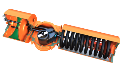
A typical Scotch yoke valve actuator
Automation Systems
Scotch yoke mechanisms offer compact, repeatable linear motion, optimal for automation systems. They provide smooth harmonic motion that allows precise timing and control.
Low part count improves reliability and reduces assembly complexity. High force capability in a small footprint benefits indexing and clamping tasks. Straightforward geometry means cost-effective 3-axis machining and high repeatability. This applied across, and between batches and suppliers.
Pumps and Compressors
Scotch yoke drives deliver very smooth reciprocating motion for pumps and compressors. The predictable harmonic profile supports consistent flow/pressure and reduces vibration sources.
Their compact format suits space-constrained systems. They provide the higher force required in handling viscous fluids and compression loads. Compensating design-elements mean better handling of side loads. Improved high-load performance comes with needle roller pin bearings, and larger slider bearings.
Reduced component count simplifies maintenance. Minimized power train parts improve reliability in continuous duty cycle operations.
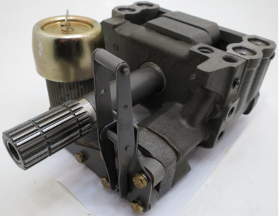
A typical Scotch yoke driven hydraulic piston pump
Robotics Motion Systems
Scotch yokes provide the same compact, precise linear motion in robotics. Micro-motion under tight control results from the smooth and predictable harmonic output. This simplifies trajectory planning.
It delivers the high force needed for grip and actuation. Low part-count reduces weight/size in motion. Close-coupled motion conversion allows position/force consistency. This makes Scotch yokes ideal for end-effectors and compact positioning actuators.
Energy Harvesting and Test Rigs
They provide controlled, repeatable motion with a predictable harmonic profile. This is needed for mechanical test rigs. Simple geometry enhances measurement accuracy/repeatability. They also provide low-loss power conversion that suits energy harvesting applications.
High force capability works well in load simulation equipment, requiring upgraded bearings. The compact layout suits laboratory and on-site instruments.
Advantages of the Scotch Yoke Mechanism
The benefits offered by use of Scotch yoke mechanisms make this a mechanism-of-choice. They deliver:
- Great mechanical simplicity
- Compact motion conversion for space constrained applications
- Potential for compact, high force solutions
- Smooth harmonic output, where precision is paramount
- Fewer components, lower costs, and easier sourcing
Disadvantages of the Scotch Yoke Mechanism
However, there are many applications where their suitability is marginal:
- High risk of slot wear requires complex bearing solutions. This causes cost/space challenges
- Friction and heat cause problems in cryogenic and high sensitivity scientific applications
- Noise at high speeds can be a problem
- Stick-slip at low speeds causes cogging. The frictional loading on the pin/slot bearing varies with position
- Hysteresis can be disruptive, under high wear conditions
How to Design a Reliable Scotch Yoke
While simple, slotted link mechanisms demand careful design to deliver effective solutions. Design and machining errors can result in very poor performance and high wear.
Factors Affecting Scotch Yoke Mechanism
Design success depends on:
- appropriate load cycles
- effective lubrication
- suitable material pairing
- alignment/precision
1. Define Requirements
Start by defining:
- stroke length
- load (N or kN)
- cycle rate
These factors drive geometry and material selection.
2. Size the Geometry
Select crank radius and slot dimensions.
- Larger radius requires a longer stroke
- Wider slot reduces risk of binding but risks increasing backlash
3. How to Control Wear
Key wear/resilience strategies are:
- hardened steel pins
- replaceable wear inserts
- lubrication grooves
Surface treatments can improve pin/slot hardness:
- nitriding
- DLC coating
4. Align and Verify
Misalignment is the key driver of wear, sticking and failure.
Each application will have its own appropriate limits. Confirm:
- guide parallelism
- pin perpendicularity
- assembly backlash
5. Design of the Slot and Pin Mechanism
It's important to avoid:
- sharp internal corners
- tight fit at any point in the cycle
Add:
- fillets appropriate to the component scale
- relief galleries to retain and distribute lubrication
CNC Machining the Key Scotch Yoke Parts
In general, all parts of a Scotch yoke have simple geometry that is easily machined. However, the machining must maintain moderate to tight tolerances and high quality finish. For product design teams, this means lower BOM complexity and easier sourcing through partners like Tuofa CNC Machining, when scaling production.
Machining the Yoke Slot
The simple, but critical requirements are:
- precise milling
- deburring
- surface finishing to a high standard on bearing/sliding surfaces
General tolerance applies, but tighter targets are best used in bearing areas. Consider limits of:
- width of slot: ± 0.01 mm
- finish: Ra 6 µm
Machining the Crank Pin Features
It is effective to focus on:
- concentricity
- surface hardness
- smooth finish
Its necessary to use:
- grinding for final sizing
- fillets to reduce stress concentration
Inspection Points That Matter Most
|
Feature |
Target |
Why is it important |
|
Slot straightness |
0.02 mm |
Smooth motion requires a straight slot |
|
Guide parallelism |
0.01 mm |
Skew forces risk locking the mechanism |
|
Pin diameter |
± 0.005 mm |
Poor accuracy lead to binding or looseness |
|
Hole position |
0.01 mm |
Radial placement of the pin defines the stroke |
|
Backlash |
0.02 mm |
Hysteresis leads to unsmooth motion |
CMM inspection at high sample rates is recommended, while production settles down.
Conclusion
The Scotch yoke mechanism delivers precise, compact linear motion. It requires care in design and high quality machining, such as that provided by Tuofa CNC services.
Well designed, Scotch yokes achieve wear resistance, easy alignment, and ease-to-make parts. This results in an effective motion device for a wide range of applications and scales.
FAQs About the Scotch Yoke Mechanism
What is a Scotch yoke mechanism used for?
It converts rotary into linear motion, for smooth, repeatable, and compact mechanical function. This is used in valve actuators, automation equipment, and pumps.
Why is it called a Scotch yoke?
The first use is uncertain, originating with early references in machinery originating in Scotland.
 CNC Machining Support for Mechanical Capstone Project Prototypes