Tel/WeChat:
  Email:
 Home
HomeMotor Shafting Made Simple: Process, Types & Custom Options

 Published:Jul 16,2025
You know everybody has a core part in it, e.g., the spinal cord in human bodies. Like human bodies, every machine contains a core part which helps it work efficiently. In this article, you are going to study a core part of many machines, which is a motor shaft. If we tell you in simple words, a motor shaft is the reason why the four wheels of a vehicle rotate together. So, let's start with its brief introduction:
What Is a Motor Shaft? -Basics & Key Functions
As you know, a motor shaft is a core part of a machine which is in a cylindrical shape. It is a bridge between the power and the real-life applications in the machines, such as transferring mechanical power to the connected parts. High-strength steel and alloys are the common choices to make a motor shaft because of the high-strength requirement. Its primary functions as listed below:
- Torque Transmission
- Structural Support
- Precision Movement
Convert Motor Torque to Work
It is the most important function of a motor shaft in any machine. As the motor spins, the shaft transforms this mechanical force or torque into connected parts such as gears, belts, etc. You can choose dimensions, material, etc., based on torque requirements, because these shafts enable machines to perform operations such as lifting, drilling or driving.
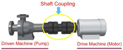
Support Bearings and Couplings
A motor shaft works with the support of the following components:
- To reduce friction and maintain smooth friction while handling axial and radial loads, a bearing is used in a motor shaft.
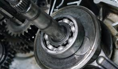
- To handle minor misalignment and force transmission issues, couplings do the job as they are joints between the shaft and other machinery components.
Transfer Motion with Minimal Vibration
To transfer motion to connected parts with minimal vibration, a motor shaft is a very important component. Because you know, a little imbalance can cause harmful vibrations, reducing efficiency and increasing the risks of wear in bearings and connected parts.
What Are the Key Design Parameters on Motor Shafting?
Before manufacturing a motor shaft, the following parameters are important to consider:
Load & Torque Calculations
As you know, it is the primary function of a motor shaft; that's why 100% accuracy is required in load and torque calculations to design a high-quality shaft. Additional stress analysis is required in case of threaded sections to prevent fatigue on these threads. You will calculate three things for load & torque calculations:
- Torque Requirements
- Bending Moments
- Safety Factors
Critical Speed and Deflection
Let us tell you that the critical speed of a shaft means the velocity at which vibrations amplify due to resonance. If the shaft exceeds this speed, the risks of severe damage are high. That's why calculate the following things first:
- Natural frequency adjustments
- Stiffness-to-weight ratio
- Finite element analysis
Bearing Fits
You know the function of bearings already. Its size must be optimum to precisely fit over the shaft. Key standards include:
- ISO tolerance grades
- Interference fits
- Clearance fits
Surface Finish Targets
The different areas of a motor shaft require different types of surface finishes, as discussed below in the table:
|
Application |
Surface Roughness (Ra, μm) |
Purpose |
|
Bearing Seats |
0.4 - 1.6 |
Ensures a tight bearing fit & reduces wear |
|
Seal Contact Areas |
0.2 - 0.8 |
Prevents leaks & extends seal life |
|
General Machined Surfaces |
1.6 - 3.2 |
Balances cost & performance for non-critical zones |
|
High-Speed Sections |
≤ 0.4 |
Reduces drag & heat generation in high-RPM applications |
|
Corrosive Environments |
0.8 - 1.6 |
Combines smoothness with corrosion resistance |
Popular Motor Shaft Types
You will study some common types of motor shafts and their functions in this section:
Solid vs Hollow Motor Shaft
You can study a brief comparison between a solid and hollow motor shaft:
|
Type |
Advantages |
Disadvantages |
Applications |
|
Solid |
Higher torque capacity, more rigid |
Heavier, no internal access |
Industrial motors, high-load systems |
|
Hollow |
Lighter weight, allows wiring/cooling |
Lower torque resistance |
Robotics, aerospace, servo motors |
Keyed & Splined Motor Shaft
- Keyed Motor Shaft
The key motor shaft uses a groove to lock gears to prevent slippage under high torque. It is common in industrial drives.
- Splined Motor Shaft
It comes with a large number of axial grooves for adjustable gear positioning, commonly used in automotive transmissions and heavy machinery.
Tapered & Threaded Motor Shaft
- Tapered Motor Shaft
Its designs gradually narrow and ensure self-locking. It is commonly used in conveyor belt drives.
- Threaded Motor Shaft
It uses nuts or bolts to directly attach components and commonly used in fans, impellers, etc.
Stepped Multi-Diameter Shafts
- You can accommodate different bearings/pulleys on one shaft
- You can reduce assembly complexity in multi-stage gearboxes
End-to-End Manufacturing Motor Shafting Workflow
You will study a step-by-step workflow from designing to the final product in this section:
1 — CAD Model and FEA Check
First, your shaft design undergoes 3D modelling and Finite Element Analysis (FEA). This step ensures:
- Optimal load distribution
- No stress concentration risks
- Confirmation of critical speed limits
You get a virtual prototype before any metal is cut, saving time and cost.
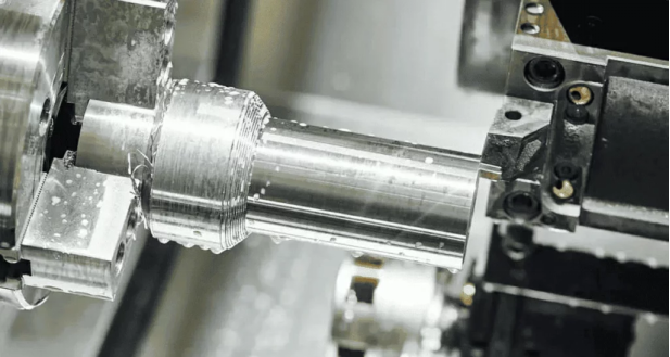
2 — Rough Turning Between Centres
After digital designing and testing, your workpiece gets into real-life machining. The first process is rough turning which gives initial shape by:
- Uniform Material Removal
- Minimal vibration during cutting
- A strong foundation for the final dimensions
3 — Milling/Drilling Keyways or Flats
Next operation is milling or drilling, which provides keyways, splines or flats according to your requirements. Our CNC milling ensures:
- Perfect alignment for torque transfer
- Burr-free edges to prevent stress risers
- Consistent depth and width per your specs
4 — Heat Treat & Stress Relieve
Your shaft undergoes heat treatments to enhance durability:
- Hardeningincludes induction, case hardening, or through-hardening
- Temperingto reduce brittleness
- Stress relievingto prevent warping
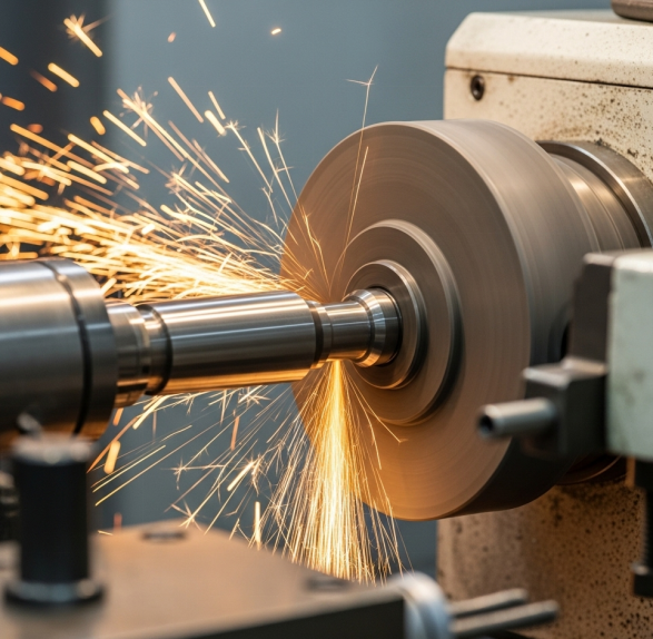
5 — Finish Grind to Tolerance (≤ 0.01 mm)
In the last step, you will perform grinding to achieve tolerances:
- Ultra-tight tolerances as low as 0.005 mm
- Mirror-like surface finishes, if required
- Perfect roundness and straightness
Now, your shaft is ready for assembly.
Quality Control in Motor Shafting Machining
You can use the following quality control measures to make sure your motor shaft remains flawless:
- Ra is measured with profilometers by using surface finish inspection
- For vibration-free operation, Dynamic balancing tests are performed
- To ensure batch consistency, you can perform Statistical Process Control (SPC)
CNC Techniques for Custom Precision Motor Shafting
Tight tolerances, superior surface finish and complex geometry can be achieved by using the CNC machine. These are the following different techniques used to make precision motor shafting:
Custom Motor Shafting Applications
Due to due to tight tolerance and minimum vibration, custom motor shafts can be used for the following applications:
- Custom drone motor shaft:
Custom drone motor shaft has properties like high strength to weight ratio, minimum vibration and tight tolerance, which helps prevent the motor shaft from harmonic resonance during high speeds. To prevent the custom drone motor from corrosion and wear, nickel and anodising coating are done on the material.
- Surgical robot joint motor:
High precision and quality control are necessary for surgical robot joint motors. For surgical robot joint motor or medical applications, a rough surface speed of 0.2μm Ra and high tolerance is maintained to ensure quality for this.
- Ultra-High-Speed CNC Spindle Shafts:
During ultra-high speed, there is always a chance of to change in the dimension of the material. Cobalt is a material that provides hardness, wear resistance and avoids deformation at ultra-high speeds in materials. To avoid this change in dimension of material, a high tool steel with 8% cobalt content is used.
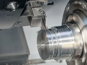
CNC Turning for Grooves:
CNC programming makes it flexible to make the grooves on cylindrical workpieces. CNC machines make it easy to do the customised and standard grooves on materials. Through these customised and standard grooves, snap rings, seals, and O-rings can be made that can be used in the automotive and aerospace applications.
Cylindrical Grinding (to 0.4 µm Ra)
This type of ultra-fine grinding can be done by grinding the material on a diamond wheel at high speed. But vibration is a problem due to high speed; this can be minimised by using the hydrostatic spindle bearing. This type of ultra-fine surface finish can be used for aerospace applications like hydraulic rods.
Wire EDM for Blind Splines
Blind spline is an internal groove before reaching the end of the workpiece. Wire electric discharge machine is an advanced technique to make blind splines. To make the blind splines, a thin electrically charged wire is used to cut/erode the material. To cut the hard metals such as titanium, high potential current is used to erode the material easily.
Five-Axis Milling on Complex Ends
It is very easy to make complex geometries, such as turbine shaft ends, from five-axis milling. Five-axis milling has three X, Y,Z linear axes and two rotational A, B axes. Due to the more angles it has as compared to a simple machine, the time for machining is reduced significantly.
Various Material Choices for Motor Shafting
Depending upon the application of motor shafting, different types of materials such as alloy steel, stainless steel, and aluminium can be used. Some of them are discussed below:
1045 / 4140 Carbon-Alloy Steel
Chromium and molybdenum are added to this medium carbon steel. It is used where moderate strength and medium stress resistance are required. This type of material has properties such as high machinability and fatigue resistance, which make it ideal to use in load-bearing industrial shafts. Rusting is a major problem with this type of steel, but this can be avoided by using the protective coating.
17-4 PH Stainless
This type of stainless steel has high hardness as well as corrosion resistance. Due to precipitates production and heat treatment done during manufacturing, that leads to makes him ideal to use in the motor shafts and marine shaft applications.
7075-T6 Aluminum
It has high strength, lightweight and stressed application due to solution heat treatment, artificial ageing and the presence of zinc as a major alloying element. Due to this treatment, it can be used for high-speed and lightweight motor shafts.
Ti-6Al-4V & Inconel 718
Ti-6Al-4V is an alpha-beta titanium alloy with high strength, good corrosion resistance and biocompatibility. Inconel 718 is a nickel and chromium alloy which can be used for high-temperature applications. Both have good corrosion resistance, but Inconel 718 is good to use for high-temperature applications. While Ti-6Al-4V can be used where lightweight durability is essential.
Finishing Processes for Motor Shafts
Surface finishing is the last process which is done after the production and machining of motor shafts. The major properties we get after finishing are wear and corrosion resistance. Depending upon the applications, these are the following methods used for surface finishing:
Hard Chrome vs Electroless Nickel
High hardness can be achieved through the chrome plate, while medium hardness can be achieved through electroless nickel plating. Hard chrome coating provides a hard coating that can be used for the abrasive environment, while electroless nickel plating can provide chemical resistance with uniform thickness on the material.
Gas Nitriding
Gas nitriding is done where a hard surface and soft core are required, such as in an industrial motor component. It is done by diffusion of nascent nitrogen on the steel surface. On the surface of the steel, a brittle coating is produced. This can be avoided by placing the steel at a high temperature to avoid the concentration gradient.
Anodizing Options for Aluminum Shafts
Anodising is done on the aluminium shafts to increase the corrosion resistance of the material. This is done by the formation of alumina coating on the surface that protects the material. Shot peening is done on the material to increase the fatigue life of the material by increasing the compressive stresses. This is basically done by bombardment of hard particles on metal but post surface finishing is done for the racing crankshafts.
Cost Considerations in Shafting CNC Machining
Cost related to CNC machining for shafting is discussed in detail below:
Machining Process
The cost of machining in shafting all depends on the application. More precision and accuracy lead to a higher cost of the process. Different processes have their own costs. Cost can be increased due to setup, machine initial charges, and maintenance charges. Processes like milling, grinding, and multi-axis machining have a high cost of machining as compared to the turning method, but more cost methods have higher precision.
Materials Cost
The total cost of parts depends on the cost of materials. Aluminium, Low and medium carbon steel like 1045 is very easy to machine that's leads to a decrease in cost as compared to stainless steel (17-4PH). But materials like Ti-6Al-4V and Inconel has low machining speed that's leads to increase in total cost of material.
Batch Size vs Unit Cost
Batch size and unit cost are directly proportional to each other. Because if there is a smaller batch size, it will automatically lead to an increase in the setup and fixturing cost. So, a large batch size is more beneficial to get a lower cost per unit.
Conclusion
Motor shaft is a critical component that needs to be designed, selected material, produced, machined and surface finished. The total cost of materials depends on the materials selected and the production method. If there are more precision requirements, then machining should be done with a five-axis milling machine as compared to other machining processes. It's all dependent on the application because if there is a more corrosive environment, then you need to coat the material with corrosion-resistant material.
FAQs
What is the standard tolerance for motor shaft runout?
Tolerance of motor shaft runout depends on the precision system. However, standard tolerance is a range between 0.025-0.05 mm (0.001-0.002 in).
What causes excessive shaft vibration, and how can it be fixed?
The major cause of excessive shaft vibration is not to choice of system according to the speed of the shaft. This will lead to imbalance and misalignment problems, and it can be fixed by rebalancing and realigning.
How to check the motor shaft runout?
Motor shaft runout can be checked by using the dial indicator. It worked by mounting the magnetic base that measured the deflection of the rotating shaft.
 Design For Manufacturing: A Practical CNC DFM Guide