Tel/WeChat:
  Email:


 Home
HomeEfficient Part Design: Tips for Reducing Cost and Improving Parts Quality

 Published:Jun 02,2026
The lapses in part design pose serious challenges in manufacturing, assembly, and functionality. An efficiently designed part saves a lot of time and cost. In this article, we will explain what is efficient part design and guide you to optimize your part design for machining.
Why Efficient Part Design Matters in CNC Machining?
Efficient part design is important for CNC machining because it can improve efficiency from the following aspects:
- Standard design features like fillet, relief grooves, etc.
- Easy-to-machine custom features like special holes, grooves, thread holes, etc.
- No too tight tolerance like ≤±0.005 mm.
Therefore, efficient design for machining can increase processing speed and shorten lead time. What’s more, efficient part design can reduce machining costs by eliminating unnecessary design features.
|
Efficient Part Design |
Lower Manufacturing Cost |
Reduce Machining Time |
Shorter Lead Time |
Better Part Quality |
|---|---|---|---|---|
|
Simple geometry |
Less machining work |
Faster toolpaths |
Faster production |
Fewer errors |
|
Standard features |
No special tools needed |
Less tool changing |
Easier scheduling |
More consistent results |
|
Reasonable tolerances |
Less inspection and rework |
Easier to machine |
Fewer production delays |
Better yield rate |
|
Tool-friendly corners and radii |
Avoids special machining |
Better cutter access |
Faster setup |
Cleaner edges and surfaces |
|
Proper wall thickness |
Less deformation and scrap |
More stable cutting |
Less rework |
Better dimensional stability |
How to Achieve Efficient Part Design?
Achieving an efficient part design is critical in ensuring:
- Functionality
- Manufacturability
- Cost Effectiveness
It helps to address challenges early on. A few key principles help in achieving efficient CNC manufacturing product design. In general, CNC manufacturers provide feedback of the part design (DFM review) for customers by considering the following factors:
- Achievable Functions
- Executable Machining Strategy
- Assembly Requirements
- Reasonable Tolerance
Then you can optimize your part design based on the feedback from the CNC suppliers. In the following content, we explain why and how functions, geometries, tolerance and assembly features affect the efficiency of part design.
Function-Oriented Design
Efficient part design values functionality over aesthetics. Cosmetic features possess only a secondary value. Therefore, the manufacturability of all unnecessary design elements should be evaluated. If it incurs a difficulty in manufacturing they must be eliminated. Operational requirements must be met.
For example, you want to manufacture a part with threads for assembly, in this case, the thread shouldn’t be eliminated. Even, you should confirm the specifications and standards for threads with the CNC manufacturers to make your parts produced successfully.
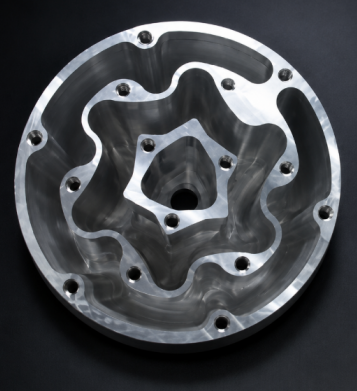
Optimize Complex Geometry
Design elements that are difficult to machine should be replaced with easily machinable elements. Examples of difficult-to-machine features include:
- deep pockets
- narrow cavities
- sharp internal corners
- undercuts
They should only be included in CAD if they are an utmost necessity. Design features must accommodate tool accessibility. They should be manufacturable with a minimum number of machining operations. Design reiterations should focus on design simplification. As a rule of thumb, simpler yet functional geometries are more efficient in design.
Optimize Tolerance
Too broad tolerance or too tight tolerance can influence part assembly. Too broad tolerance can reduce cost while tight tolerance can increase machining cost. The maximum reasonable tolerance that ensures functionality should be adopted.
|
Too Broad Tolerance |
Too Tight Tolerance |
Reasonable Tolerance for Efficient Part Design |
|---|---|---|
|
May cause loose fits and assembly misalignment |
Increases machining and inspection cost |
Ensures proper fit and function |
|
Can create vibration, leakage, or inconsistent performance |
Requires slower machining and more setups |
Controls only critical features tightly |
|
May reduce part-to-part consistency |
Increases scrap and rework risk |
Uses standard, achievable tolerances where possible |
|
Can affect sealing, motion, or load transfer |
Extends production time and lead time |
Uses the widest tolerance that still meets functional requirements |
|
Example: a bearing bore is too loose |
Example: ±0.005 mm on a non-critical surface |
Example: tight tolerance on a mating bore, standard tolerance on other surfaces |
Optimize Assembly Design
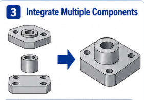
An efficient part design should facilitate the assembly of components. Ideally, components should be self-aligning. They can have alignment guides. If multiple components are integrated into a single component, it'll save time in assembling. It will also prevent the compounding of tolerances. Symmetrical designs are easier to fit than asymmetrical ones. Holes and slots should be standardized. Non-standard holes require customized tools.
How to Design Parts Based on Functional Requirements?
Serving the intended function is the foremost requirement of an efficient part design. A good designer must consider the design from all perspectives. The part must be fully functional in the destined operating conditions. To achieve it, the CAD and BOM must be well considered. It helps to generate an efficient design for manufacturability.
Identify the Key Functions
An efficient part design encompasses all aspects of functionality. A part may be required to transfer motion, to seal fluids, or to maintain alignment. Whatever it may be, manufacturing designs should accommodate key functions. In addition to maintaining functionality, an efficient part design should eliminate all unnecessary design elements.
Consider the Operating Environment
Consideration of the operating environment is another important aspect. Even if design accommodates key functions, negligence of environmental conditions would render the parts useless. As an example, a design part that does not have suitable thermal expansion allowances, might fail above a certain temperature. Another example could be of an uncoated tool subjected to harsh abrasion. Would it be hard coated, it could withstand the environment. There are many more examples. It's just the designer's skills that help to achieve an efficient part design.
Select Suitable Materials
At times the properties of a material play a role more vital than all other factors. As an example, titanium with its excellent strength to weight ratio is a celebrity in aerospace parts. If steel is to be used in its place, it's high density might fail the overall aerodynamic design. In another scenario, if a copper busbar with a high conductivity is replaced with some mediocre like stainless steel, it might fail its primary function. So, selection of suitable materials is as much critical as functionality.
How to Optimize Complex Geometry in Part Design?
Complex geometries with no functional value are undesirable in efficient part design. CNC manufacturing product design should be well optimized. Unnecessary features that are difficult for machines to handle should be eliminated.
Simplify by Combining Parts
An integrated part design is generally more efficient than separate parts. It reduces assembling operations, fastening requirements, and compounding of tolerances.
Eliminate Unnecessary Features
All unnecessary features that have no functional value should be minimized. The functional features should be prioritized. At times, some cosmetic features like grooves, engraving, or curved surfaces pose considerable difficulty in machining.
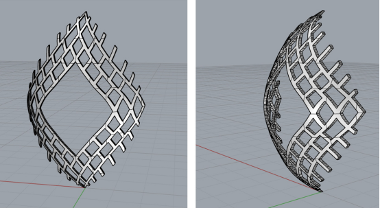
Here provides an example:
In the practical case of Tuofa, our client wanted to make a part with irregular curved surfaces, which could cause long time to do that. However, the client wants to shorten the lead time. Therefore, we recommended that the client simplify the surface. The change was accepted by our client, and the machining time is shortened without compromising the functions.
Avoid Difficult-to-Machine Features
Design simplification is sought for efficient part design. If substitutes are present, then difficult-to-machine features should be eliminated. Narrow cavities, sharp internal corners, undercuts, thin walls, and small holes should be substituted with machinable features.
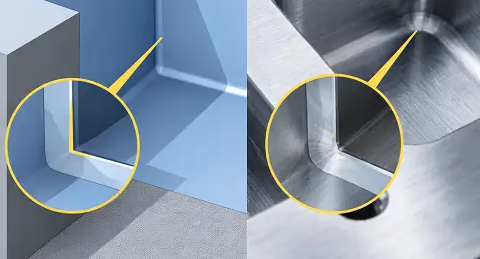
Here is a typical example:
Sharp corner is always avoided because it be hardly machined. CNC milling uses rotating tools, so the machined corners naturally become rounded. If the sharp corner can influence the functions of parts, it is better to machine this feature through EDM machining.
How to Optimize Tolerances to Reduce Cost?
Apart from some other key areas of cost-cutting, tolerance optimization is also an important aspect. Engineers optimize tolerances to make part design efficient. It not only cuts costs but also shortens lead time.
Apply Tight Tolerances Only to Critical Features
Maintaining tight tolerances is often effort-consuming. They may require additional machining operations, finishing processes, and inspection controls. So, applying tight tolerances to non-critical features would inadvertently increase cost, lead time, and rejection rates. If tight tolerances are specified only for critical features, then manufacturers can focus mainly on those critical areas. Some examples of critical areas include:
- bearing seats
- mating surfaces
- sealing areas
- alignment holes
Avoid Tolerance beyond Manufacturing Capability
While specifying tolerances, manufacturing capabilities should be well understood. Tolerances beyond this capability pose serious manufacturing challenges. They may require to involve advance processes, additional inspections and a stringent process control. Even then, the rejection rate would be above expectations. All of this is cost-intensive.
Consider Tolerance Stack-Up in Assembly
In some scenarios, dimensional variations exceed the tolerance limit even if the manufacturer supplies parts within the limit. This happens due to the accumulation of dimensional variations of parts during assembly. An efficient part design considers this problem. Designers may simplify designs or integrate components to alleviate this issue.
How to Design Parts for Easy Assembly?
Efficient part design facilitates ease of assembly. It focuses on minimizing assembly errors and improper fit. Design features are included in CAD that help in this goal. Multifunctional part design, inclusion of self-locating features, and adoption of poka yoke ease the assembly of parts.
Minimize Part Count
The fewer the number of parts, the fewer the chances of assembly mistakes. Efficient part design emphasizes reducing part counts. Fewer parts mean fewer handling operations, reduced inventory management, simplified logistics, and shorter assembly times. This efficient part design can be achieved by creating integrated and multi-functional parts.
Use Self-Locating Features
Self-locating features minimizes manual adjustments for assembly. Parts fit on the location where they are intended to be. Common self-locating features include:
- Guides
- alignment pins
- tapered edges
- chamfers
- slots
- guide rails
- interlocking features.
Design for Poka-Yoke
Poka Yoke is an error prevention strategy. It focuses on minimizing human errors during installation. Common errors include reversed installation, incorrect positioning, or missing components. Poka Yoke efficient part design includes features that prevent errors. As an example, asymmetrical hole patterns would prevent incorrect orientation of fitting components. Color-coded interfaces match the correct mating surfaces. One way assembly prevents reverse installation. There are many other such strategies.
Common Mistakes in Part Design
Some mistakes pop up in design even after careful consideration. These mistakes are common and recurring. It is advisable to look for these mistakes in design. Even small mistakes can dramatically affect the performance of parts.
Improper Clearance Hole Design
A common mistake is to specify improper clearance for holes. If the clearance is too tight, then it creates hurdles in machining and assembly. If clearance is too loose, it can cause alignment and fitting issues. Efficient part design optimizes the clearance of holes in the design.
Design Sharp Internal Corners
CNC machines naturally create rounded internal corners. Sharp corners are very difficult to create. They might require additional processing. Not only that, sharp internal corners bring stress concentration, which weakens the structure. Ideally, corners should be filleted with a radius matching the standard tools.
Improper Corner Radius for Pocket Depth
Corner radius should match the pocket depth. If the corner radius is small and the pockets are deep, it'll require long and narrow tools. That is not the only problem. Maintaining a consistent machining operation with these tools is difficult. It is best to specify corner radii proportional to the pocket depth.
Prototyping for Efficient Part Design
The true validation of a so-called efficient part design can occur only by testing the prototype. The hidden complications in functionality, assembly, and manufacturability are revealed by testing the prototypes.
Validate Functional Performance
Although simulations and finite element analysis (FEA) give a useful insight into product functionality. But testing of the actual prototype under real operating conditions might reveal some other lapses. The true functional performance of a design can only be obtained by testing the prototype. This helps designers to reiterate designs. These reiterations facilitate attaining an efficient part design.
Validate Assembly Performance
Even if a part is functionally sound, it might pose challenges in assembling. Fit, function, and performance metrics are thus critical. The performance of the integration of parts and self-aligning features is also evaluated by assembling prototypes.
Validate Manufacturability
A part that functions correctly might still be difficult to machine. A CAD file cannot fully comprehend these challenges. Only the manufacturing of a real prototype reveals the real issues in manufacturing.
Efficient Part Design Checklist
A good practice is to evaluate a design against a checklist. Critical evaluation parameters included geometry, assembly, manufacturability, and tolerances. The tables below provide checklists for design evaluation.
Geometry Checklist
|
Features |
Guideline |
Reason |
|---|---|---|
|
Wall thickness |
Keep it uniform |
It prevents distortion |
|
Radii |
Use internal fillets |
Improves strength and tool access |
|
|
Avoid deep pockets |
Reduces tool deflection |
|
slots |
Design with standard cutter widths |
Ensures easy machining |
|
Holes |
Standard drill sizes |
Lowers cost and simplifies tooling |
|
Edges |
Improves assembly |
|
|
Symmetry |
Use symmetric geometry when possible |
Reduces setup complexity |
Tolerance Checklist
|
Features |
Guideline |
Reason |
|---|---|---|
|
Critical dimensions |
tight tolerances only on functional features |
Controls cost and complexity |
|
Standard Tolerances |
Use general tolerances on non-critical areas |
It enhances manufacturability |
|
Fits |
Define clearances |
ensures correct assembly |
|
inspection |
Specify measurement method |
QC reliability |
|
Stack -up |
Analyze cumulative tolerances in assembly |
it prevents misalignment issues |
|
GD&T |
Use GD&T for complex features |
Improves geometric clarity |
Manufacturing Checklist
|
Features |
Guideline |
Reason |
|---|---|---|
|
Material |
Based on operating conditions |
Avoids over or under engineering |
|
Process |
Match design to manufactruing method |
controls cost |
|
tool access |
Ensure cutter reach |
it prevents unmachinable features |
|
Setups |
reduce number of setups |
Reduces error risk |
|
Standard features |
Use standard tools |
simplifies sourcing |
|
Finishing |
Specify only required finishes |
Avoids unnecessary cost |
Assembly Checklist
|
Features |
Guideline |
Reason |
|---|---|---|
|
Part count |
Reduce number of parts |
Lowers assembly time |
|
fasteners |
Use standard types |
it simplifies assembly |
|
Alignment |
Add locating features |
Improves repeatability |
|
Access |
Ensure tool clearance |
avoids installation issues |
|
Mistake- proofing |
Add poka - yoke features |
Prevents incorrect assembly |
|
Modularity |
Group into subassemblies |
Easier maintenance |
One-Stop Solution from Design to Manufacturing
Clients are always eager to find a complete design and manufacturing solution. If a CNC manufacturer can provide design support, it's a great blessing. A company that undertakes the responsibility of aligning CAD with DFM gives minimal errors in communication. A well-communicated manufacturing job leads to perfection.
Tuofa DFM Support
Tuofa welcomes inquiries for CNC machining orders. Our dedicated teams review the CAD for design for manufacturability. They review it for manufacturability, material selection, assembly, and functionality. Please feel free to avail our DFM support for your designs. Our professional feedback would help to turn your design ideas into reality.
Tuofa provides DFM support by:
- Checking dimension
- Checking tolerance
- Analyzing if the features are suitable for machining
- Evaluate materials
- Evaluate surface treatment
CNC Machining Capabilities for Custom Parts
Tuofa has a wide range of manufacturing capabilities that align with the custom production of parts. Our well-equipped machine shop can carve out complex geometries within tight tolerances. We offer a lot of finishing operations as per design requirements. The biggest advantage of opting for our custom part production is the quick movement from prototyping to mass production.
Conclusion
Efficiently designing parts brings a lot of enhancement in manufacturing and functionality. Efficient designs are cost-effective and quicker to produce. Whereas, poor design brings manufacturing difficulties and often neglects the true functionality of parts. Efforts must be put into refining designs until an efficient part design is created. It'll minimize errors manifold in subsequent manufacturing.
FAQ
How can I improve my CAD skills?
Practice will make you perfect. Opt for creating CAD from online tutorials. Get help from professionals.
How to design a part for CNC machining?
Consider the machining capabilities of a CNC machine. CAD software can create any features that you want. But you need to make sure that they can be machined by the CNC machines.
What is the difference between part design and assembly design?
Part design is for a single component. Assembly design is the cumulatively assembled design of components.
 How to Design Your Aluminum Casing for Electronic Devices?