Tel/WeChat:
  Email:
 Home
HomeSTEP File Guide for Engineering Beginners

 Published:Apr 03,2026
Clients often need to brief the suppliers about their designs. Quite often, there can be a mismatch between the native CAD software of the clients and the suppliers. STEP files solve this problem. If a CAD is exported as a STEP file, it can be opened in almost any CAD software. It doesn't matter whether the file was created in SolidWorks or CATIA, it becomes system independent. Files can thus be created in one CAD software and opened and edited in another. So, clients planning to get a quote should export the CAD in STEP file format. It gives CAD the universal accessibility to be opened anywhere.
What Is a STEP File
.STEP file format is a universal file format compliant with ISO 10303. It is widely used for sharing and modifying CAD files. STEP files store both surfaces and solids. STEP files are instrumental in preserving design intent. It saves a complete record of geometry, dimensions, tolerances and assembly hierarchy.
STEP File Definition
STEP is abbreviated for "standard for the exchange of product data. It is a 3D CAD file format that is system independant. STEP files can run on multiple CAD platforms like SolidWorks, Fusion 360, AutoCAD, etc. It means that whichever CAD software is used, STEP files can be created, modified, transferred, and viewed. STEP file format stores more information than its predecessors, like IGES and STL. This ability preserves the original design intent better than other formats.
STEP vs STP File Extensions
"STEP" and "STP" are essentially the same file formats. There is no difference at all. CAD softwares treat both STEP and STP files identically. The difference is due to a naming convention. Older operating systems required 3-letter extensions. So, back then, this file extension was called STP. But now, the need to stick to 3 letters only is no more. So, in modern systems, it is called a STEP file.
Why STEP Is a Common CAD Exchange Format
STEP file is considered the most common CAD exchange format. It has an enormous ability to interoperate between different CAD platforms. So, it STEP files can be opened and edited on almost any common CAD software. These files preserve precise geometry and assembly relationships. That too happens with negligible risk of data loss or corruption. As an example, a CAD model created in SolidWorks, saved as a STEP file, can be opened and edited in other CAD software like AutoCAD, etc.
STEP File Format Basics (ISO 10303)
The structure of STEP files is devised by a globally agreed standard, namely ISO 10303. During its evolution, a few application protocols have evolved. These APs have their own significance.
STEP files can be stored as an ASCII or binary file. The preference for file formats depends on file size, readability, and compatibility.
What ISO 10303 Means
ISO 10303 is a standard developed by the International Organization for Standardization. Before the commencement of ISO 10303, CAD files relied on proprietary file extensions. It created difficulties in file transfer and data exchange. ISO 10303 devised a neutral structure for a universally readable CAD file format. It laid the foundation for the creation of the STEP file. Now, the structure of the STEP file is compliant with ISO 10303.
Common STEP Application Protocols
- AP203
It is the earliest application protocol. It works well in storing 3D mechanical design data. Though it has limited capabilities for storing colors and metadata, it works well even on older systems.
- AP214
This application protocol was created considering the demands of the automotive sector. It supports colors and layers. So, product visualization and rendering becomes possible.
- AP242
This is the latest application protocol. Along with the features of AP203 and AP214, AP242 supports PMI (Product Manufacturing Information) and semantic annotations.
ASCII vs Binary STEP
A STEP file can be stored in ASCII or binary formats. ASCII is human-readable but has a large file size. This readability has an important consequence. It can be debugged easily. On the other hand, the smaller file size of binary files makes them optimized for storage. ASCII is compatible with a range of software. But binary STEP files have limited compatibility. In short, ASCII is preferred due to readability and compatibility, and binary files are preferred due to low disk space occupation.
What Is Inside a STEP File
STEP files provide a structured representation of a 3D product. Instead of approximations, STEP files use mathematical modelling for accurate representation. Almost all design data gets well preserved in STEP files. Geometric features, assembly hierarchy, tolerances, colors, and PMI are stored in the STEP file. These files can be opened in various CAD software as if they are native files.
Geometry Types in STEP
Basic Points and Directions
STEP files rely on a 3D coordinate system. X, Y, and Z axes define this 3D space. The coordinate points give the exact locations. Vectors define the orientation. As an example, coordinates (1,1,1) define the location, i.e, 1 point in the x-direction, 1 in the y-direction, and 1 in the z-direction. Vectors like "extrude along a specific axis" define the orientation.
Curves
Curves define edges and boundaries. STEP file derives curves from mathematical representation rather than approximations. Commonly, lines, circles, arcs, splines, and circles are stored in a STEP file.
Surfaces
Surfaces are created by extending or connecting curves in STEP files. These files store planar surfaces, cylindrical surfaces, conical surfaces, and freeform surfaces. Due to the accurate mathematical modelling, like NURBS, .step files are better than mesh formats like STL.
Special Geometry
STEP allows specialized geometric features like trimmed surfaces, cuts, unions, and intersections. Holes, fillets, chamfers, and sketch cuts can be stored in STEP files.
How to Read Your STEP File?
STEP files are easily readable in various CAD software. At first, open or import the STEP file in a CAD software. Depending on the application protocol, data information can be accessed. As an example if a STEP file saved in AP 242 is opened in SolidWorks, all dimensions, geometric features, tolerances and colors can be read. If the OD of a cylinder needs to be inspected, use the "smart dimensions" tools in the "Sketch" mode. Just click on the circular edge to check the OD. Similarly, dimensions of any edge of a point-to-point distance can be checked using the smart dimensions tool. Just use the imported STEP file. It does not matter on which CAD software it was created.
When to Use a STEP File
STEP files are highly instrumental in seamless data exchange across different CAD platforms. It is the foremost solution for direct import into CAM. Engineers can collaborate efficiently while using different software. STEP file also paves the way for connecting CAD, CAM and CAE.
Sharing 3D Models Across CAD Systems
STEP file is an ideal file-sharing platform for collaborative environments. As an example, a CAD created in SolidWorks by designers, inspected in AutoCAD by engineers, and imported into Fusion 360 by manufacturers, can all take place by sharing STEP files. It is system independent. Moreover, the least chance of loss of fidelity or design intent during data transfer makes it promising. A well-preserved CAD makes accurate manufacturing possible.
Sending CAD for Supplier Quotes
Many suppliers request STEP files for viewing complex 3D models. It becomes especially important when dealing internationally. Although native files preserve data more accurately. But what if a supplier doesn't have the CAD software to open those native files? STEP file being universally readable provides an effective solution. These STEP files can be imported directly into CAM software for toolpath generation and CNC machining. By inspecting the intricacies of design using STEP files, suppliers can quote accurately.

If you are looking for a suitable supplier to machine some small batch parts, you may come to nearby or abroad companies, which have in-house machining services. As a reputable name, Tuofa CNC Machining can assist well with cost estimation and manufacturability analysis. Just save your CAD in STEP file format and send it to us. Our dedicated team will conduct an in-depth analysis. We check the design for machinability. If any changes are needed, we suggest it to our client. After a unanimous conclusion is reached and a contract if finalized, we start manufacturing. The quotation can include procurement, CNC machining, finishing services, and shipping. We give a reasonable lead time. Clients can advise on their payment method, such as DP, LC, or TT.
Common STEP Viewer
STEP files are universally readable. They can be imported and accessed in all common CAD software. Even if a CAD software is not available, STEP files can be opened in a STEP file viewer. Commonly, the following CAD software are used for opening STEP files:
- AutoCAD: For basic viewing and inspection
- SolidWorks and Fusion: For detailed inspection and modification
- Blender: For viewing and rendering using plugins
When Not to Use STEP
While STEP files contain the key 3D modelling data, it is not always necessary to use it. For initial discussions, sharing 2D drawings may be more appropriate. These are commonly saved in PDF format. It is easier to view and interpret. So, it saves time. But for complex designs, sharing a STEP file brings clarity in discussion and reduces ambiguity.
Common Native CAD Formats by Region
During this globalization era, a single native CAD format across the entire country is not common. Industries have access to different CAD platforms. But, owing to the historical connection of a particular CAD software with a country may have some impact on regionalization. As a result, file formats like SLDPART, PRT, CATPart, etc. are still popular in many regions. But from a truly universal aspect, only system-independent formats like STEP file or IGES allow interoperability.
Native vs Universal CAD Files
Native CAD files are system-dependent. They are intended to be used for in-house design work. If they are used on a single platform, they preserve full design history, parametric features, and constraints. But they are not fully compatible across different platforms. Universal CAD files relieve design from software-specific dependencies. File formats like .step file, .iges and .stl retain only the essential geometric features and for downstream use.
France CAD Formats
CATPart
CATIA is commonly used in France and Germany. It can handle precision designing of automobile parts for high-end manufacturers like Bugatti and BMW. CATIA is specialized and expensive. CATPart files may not be ideal for collaborative work across different platforms.

United States CAD Formats
SLDPRT (SolidWorks Part)
SLDPRT is the native file format of Solid Works. Globally, it is the most widely used native file format. It stores parametric feature history, sketches, and design intent.

PRT (PTC Creo Part)
Creo is a common CAD platform across Japan and South Korea. Its native file extension PRT is thus popular in the heavy mechanical industries in these countries.
China CAD Formats
As China is an export-oriented country with a strong emphasis on international collaboration, manufacturers there believe in interoperability. Most suppliers request STEP files or IGES files. But, industries can also work on native file formats if their CAD software is available.
STEP vs Other 3D File Formats
While the STEP file is now a universally acceptable data exchange format, there are other file formats as well. STEP files provide complete solid and surface geometry. Older systems like IGES and STL rely on approximations. IGES is older and gives curves and surfaces only. STL file format relies on mesh-based approximations. Other formats like OBJ and 3MF are more focused on visualization than on engineering design. The tables below compare some of the key features of these file formats.
STEP vs IGES
|
Feature |
STEP (.step / .stp file) |
IGES file type |
|
Standard |
ISO 10303 |
ANSI standard |
|
Geometry capability |
Precise solid and surface geometry |
Surface geometry with weak solid support |
|
Topology |
Fully defined |
Poor or missing |
|
Accuracy |
High precision |
May need repair |
|
Assemblies |
Supports full assemblies and hierarchy |
Limited or no assembly support |
|
Metadata |
Supports colors, PMI and materials |
Very limited data support |
|
Interoperability |
Excellent across modern CAD/CAM systems |
Good for legacy systems |
|
Post -Import Work |
Minimal cleanup required |
Often requires healing and fixing |
|
Applications |
Manufacturing, CNC, and accurate data exchang |
Legacy file sharing, and older workflows |
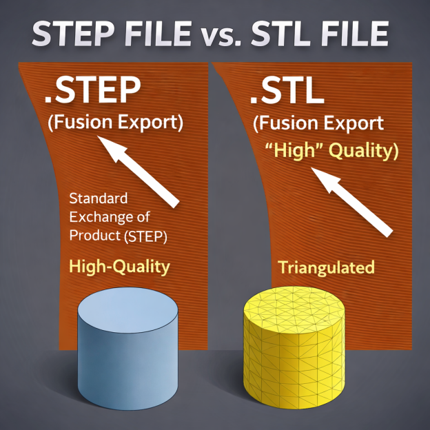
STEP vs STL
|
Feature |
STEP (.step / .stp file) |
STL (.stl file) |
|
Geometry |
Exact solid and surface geometry |
Mesh geometry |
|
Accuracy |
High precision: true curves and surfaces |
Approximate: curves represented by triangle |
|
Editability |
Fully editable in CAD systems |
Difficult to edit as Cad geometry |
|
File size |
Moderate |
Depends on mesh density |
|
Assemblies |
Supported |
Not supported |
|
Metadata |
Colors, PMI, and materials |
Very limited or none |
|
Applications |
CNC machining, CAM |
3D printing |
|
CAM Compatibility |
Excellent |
Limited |
|
Surface Quality |
Smooth and mathematically exact |
Faceted |
STEP vs OBJ and 3MF
|
Feature |
STEP (.step / .stp file) |
OBJ (.obj file) |
3MF (.3mf file) |
|
Geometry |
Exact solid and surfaces |
Mesh |
Mesh |
|
Accuracy |
High precision |
Approximate |
Approximate |
|
Curves and surfaces |
Mathematically exact |
Approximated with polygons |
Approximated with mesh triangles |
|
Editability |
Fully editable in CAD |
Limited |
Limited |
|
Assemblies |
Supported |
Not supported |
Limited support |
|
Metadata |
PMI, materials, and colors |
Supports textures and colors |
Supports colors, materials and print settings |
|
File Size |
Moderate |
Can be large |
Compressed format |
|
Applications |
Engineering, CNC and manufacturing |
Rendering, animation and visualization |
3D printing and additive manufacturing |
|
CAM |
Excellent for machining workflows |
Not suitable for machining |
Limited to additive manufacturing |
|
Strength |
Precision and interoperability |
Visual detail and Texture Support |
3D printing |
STEP Files for CNC Machining Quotes
STEP file is an ideal file format to get a machining quote. If it is accompanied by a 2D drawing, communication becomes clearer.
What CNC Shops Expect with a STEP File
CNC shops can use STEP files for direct import into CAM software for toolpath generation. To be fool-proof, professional CNC shops request STEP plus 2D drawing. While STEP files provide detailed geometric features, 2D drawings give tolerances, surface finishes, threads, and special notes. The upcoming online quoting system of Tuofa CNC machining will provide a quick quote within 30 seconds. You would need to just upload the technical drawings, set the quantity, and surface treatment. The instant quoting system will promptly generate a quote.
STEP File Checks Before You Send It
Before a STEP file is sent, make sure to check the following points:
- Ensure that the model is fully closed
- remove unnecessary geometry
- suppress cosmetic features and construction bodies
- Check units and scale
- Double-check hole sizes and wall thickness
- Simplify overly complex features
- Confirm orientation
DFM and DFMA
Consider the tips mentioned below to ensure DFM. Only a good design can cost-effectively increase productivity.
- Design around standard tooling
- Control depth to diameter ratios
- avoid deep holes or pockets
- Minimize repositioning setups
- Tight tolerances should only be applied to critical features.
- use standardized features
- Include flat surfaces that make clamping easier
STEP Files for 3D Printing
STEP files retain the exact engineering design intent, but they need to be converted to a mesh-based file format like STL or 3MF. The conversion process can be quite simple for many types of designs.
Can You 3D Print a STEP File
STEP files cannot be directly used for 3D printing. Conversion to STL or 3MF might be required. Most 3D printers require a mesh-based file like STL. Whereas, a STEP file is not mesh based.
STEP to STL Workflow
STEP files are first imported into a CAD tool or slicer. It then undergoes meshing. After the adjustment of resolution and tolerance, the STEP file is exported as an STL file. Then print settings like layer height, infill, and supports are defined. Then this file is processed for toolpath generation.
When STEP Is Better Than STL
Although STL is the go-to format for 3D printing, it is not always the best format. STEP file offers modification, editing, and fixing of errors in the CAD software. The exact curves, surfaces, and dimensions enable higher precision for complex components.
How to Convert a STEP File
Most file format conversions are quite simple. They need CAD software like SolidWorks or Fusion 360. The Step file can be exported to the required file format. But some conversions require additional parameters. For example, converting from a STEP file to an STL would require setting the resolution. Higher resolution would yield smoother curves. But it would increase the file size. STEP files can also be converted to DFX and DWG formats for 2D drawing views. It would show the top, side, front, and isometric views with dimensions and tolerances. All parametric data might not be converted.
Conversion Traps and Common Misses
Conversion errors are quite common. They can result in costly manufacturing losses. So, careful handling during export is needed. The table below shows some of the common mistakes:
|
Issue |
Impact |
Export scenario |
Remedy |
|
Precision Loss |
Curves become faceted with poor surface quality |
STEP to STL |
Use high mesh resolution |
|
Unit errors |
Wrong part size |
All formats |
check and standardize units before export |
|
Geometry Gaps |
Open edges and non-manifold bodies |
STEP to IGES |
Run geometry repair before conversion |
|
Missing details |
Features not visible in 2D |
STEP to DWG/ DXF |
Create proper views, sections, and annotations |
|
Heavy File Size |
Slow processing |
STEP to STL |
Optimize mesh density |
|
Loss of Editability |
Cannot modify design easily |
STEP to STL/OBJ |
Keep STEP file as master file for future edits |
|
Tolerance loss |
Critical dimensions not defined |
STEP to 2D formats |
Always include 2D drawing with tolerances |
|
Wrong orientation |
Incorrect print or machining setup |
STEP to STL |
Set correct orientation before exporting |
Conclusion
STEP file format is now treated as a data exchangeable format with interoperability across various systems. As it preserves the original design intent, it brings clarity in correspondences. Users can open, modify, and transfer CAD in multiple CAD software programs like AutoCAD, SolidWorks, CATIA, etc. STEP files can also be imported into CAM for CNC machining. Quite often, suppliers require 2D drawings along with STEP for quotations. Here at TUOFA, we offer great flexibility to our clients. Even if you do not have CAD or drawings, you can send us the samples. We can quote from them accordingly.
FAQs About STEP Files
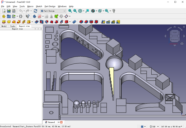
Is there a truly FreeCAD software?
FreeCAD is totally free for personal and commercial use
Can a step file be converted to dwg?
Yes, CAD software like SolidWorks, etc., can be used to convert a STEP file into DWG
Are step files used for cnc machining?
Yes, STEP files can be imported into CAM software for toolpath generation for CNC machining
Is there a free step file viewer online?
Online tools like Autodesk Viewer can be used to open step files for free.
What are assembling step files in FreeCAD?
Multiple parts can be imported in FreeCAD. They can be then positioned and constrained to make assembly.
 Brushed Parts: How to Get a Good Brushed Finish