Tel/WeChat:
  Email:
 Home
HomeCATPart Files for CNC Machining: Various Format Guide & Conversion

 Published:Jul 30,2025
Creation of complex designs for critical components can be a tantamount challenge. CATIA eases this difficulty. It is a highly powerful CAD software that can make engineering designs with ease and accuracy. The CATPart file that it creates can be sent to the CAM software via an intermediate neutral exchange format. The G Codes generated will instruct the CNC machine to manufacturing it flawlessly. Here is a complete guide related to the handling of CATPart files.
What Is a .CATPart File?
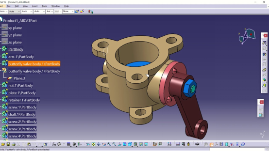
CATPart file is the native file extension type for CATIA software. It stores complete information related to modelling and product lifecycle management (PLM). Users can view and edit geometry, features, parameters, and constraints of a CATPart file using the CATIA software.
What Is CATIA?
CATIA is a high-end 3D modelling software. It was developed in France by Dassault Aviation which makes fighter jets for the French Airforce. CATIA stands for Computer Aided Three-Dimensional Interactive Application. Initially CATIA was used only for fighter jets designing. Nowadays, it can be purchased by anyone. Due to its advanced features, it is a software of choice by many high-end industries. CATIA is one of the few software that provides a unified platform for all three design functions i.e., CAD, CAM and CAE. Learn more about CATIA in this video:
Origins in CATIA V5 & V6
CATIA V5 is the most widely used version. It was the first version which could make Catpart file extension. All the data is stored locally in file formats like .CATpart, .CATproduct or .CATdrawing. CATIA V6 is an upgraded version of CATIA V5. It also supports the CATPart file. But data is stored on cloud which makes it more accessible for teamwork. It has full integration with PLM database like 3DEXPERIENCE.
Native Data vs. Neutral Exchange
CATIA generates its own file formats namely, .CATpart, .CATproduct or .CATdrawing. These file extensions open in CATIA software only. A user can view and edit sketches, features, constraints and parametric relations. If a design is to be exported to another software it needs to be saved in a neutral exchange file format like STEP. Here, only the final geometry will be exported and other things like constraints and parametric relations might be left behind.
CATPart vs STEP, IGES & Other Common CAD Formats
At times it becomes necessary to save a CATPart file in neutral exchange format. It makes it interoperable across various computers and machines. As an example, a design created in CATIA might need to be sent to a CNC router which might not read a CATPart file extension. In that case neutral exchange formats like STEP or IGES are most likely comprehendible by the CNC. The table below shows some of the common features of these file formats.
|
Format |
Type |
Editable |
Feature History |
Parametric |
Geometry Type |
CNC Ready |
|
.CATPart |
Native |
CATIA |
Available |
Yes |
Solid and Features |
Yes |
|
.STEP |
Neutral |
Limited Editability in CAD |
Not available |
No |
Solid |
Yes |
|
.IGES |
Neutral |
Only surface can be edited |
Not available |
No |
Surfaces |
Risky |
|
.STL |
Mesh |
Not editable |
Not available |
No |
Triangulated Mesh |
Yes |
CATPart vs STEP
STEP file is the most widely used file format for data transfer of 3D models. It can be read by almost all 3D modelling platforms. As compared to CATPart file, STEP file does not retain feature history or parametric data. Hence the file size becomes smaller and easier to save. Practically, designs are made in CATPart file formats. All editing and reiterations are made in CATPart extension. The final CNC ready design is then saved and sent to the vendor in the STEP file format.
CATPart vs IGES
IGES is another neutral exchange format. It used to be widely adopted for data transfer of 3D models until a few years ago. Now, it has been widely supplanted by the STEP file format. IGES is prone to lose solid model integrity. It also has precision issues. It can mess up with tolerances and gaps. So, it is considered to be a bit outdated.
CATPart vs Parasolid (x_t)
CATPart files can also be saved in the Parasolid format. It depends on the license. Otherwise, it'll be first converted to STEP file and then again into parasolid. Apart from the Euclid kernel which is used in CATIA, Parasolid is itself a geometric modeling kernel. It is used in other Software. As an example, SolidWorks which is also owned by Dassault Systemes uses Parasolid kernel while CATIA doesn't use it.
CATPart vs STL
3D models in CATPart files have solid design features. On the other hand, STL is a mesh. It used faceted triangles with approximations. As an example, CATPart file will have actual curves based on mathematic formulae. But STL will approximate triangular faces for curves. A high precision design in STL will have very small sized but a large number of triangular faces.
Opening & Viewing CATPart Files Without CATIA
CATIA is a high end 3D modeling software. Its license is a bit expensive for some companies. Big OEMs often use CATIA to produce good quality designs. However, the component manufacturer may not have access to CATIA. In that case, there are several free or low-cost ways to view, understand and interpret engineering designs. It boosts up interoperability among distinct entities.
Free/Low-Cost CATPart Viewers
3D XML
3D XML is also developed by Dassault Systemes. It is free to access. To view 3D models in 3DXML, CATPart files must be saved in the XML format. Then the XML file is sent to the manufacturer who can check the geometry, annotations, and assembly hierarchy in the 3D XML viewer.
eDrawings

eDrawings is developed by SolidWorks. It is a free viewer (for basic version). A combination of CATIA translator and drawings can be helpful in viewing designs made in CATIA. It is ideal for SolidWorks users. Details like markups, measurements, and simple analysis can be easily viewed in eDrawings.
Cloud-Based Portals for Supplier Review
At times the use of cloud-based portal becomes particularly essential in team work. For collaboration between designers, OEMs and manufacturers cloud-based portals give instant access and real time design updates. The table below shows some of the common cloud-based portals:
|
Portal |
Key Features |
|
3DEXPERIENCE ENOVIA |
Native CATPart viewing, revision control, PLM access |
|
Marketplace (Dassault) |
Supplier quoting, CATIA integration |
|
PTC Windchill |
Multi-CAD viewing via ThingWorx |
|
Siemens Teamcenter |
Views CATIA, JT, Parasolid (limited) |
|
Fusion Team |
Cloud viewer for STEP, IGES, STL; CATIA via conversion |
|
GrabCAD Workbench |
Free sharing; CATPart view via plugins/conversion |
Converting CATPart to CAM-Ready Formats
Designing in CATIA for high quality 3D modelling and then exporting it correctly to CAM software is a good strategy. It maintains precision in design and manufacturing. A few quick and easy steps can convert .CATPart files into CAM ready format that pave the way for high end manufacturing in CNC machines.
Export to STEP AP242
STEP AP242 is the latest version superseding AP214 and AP203. It integrates their capabilities while adding critical MBD functionalities. When exporting geometry, AP242 preserves full PMI data -- including GD&T, dimensional tolerances, surface finish specifications, and 3D annotations -- enabling model-based manufacturing workflows.
IGES & Parasolid Alternatives
IGES is considered to be a bit outdated. It supports wireframes, surfaces, and solids. But it cannot maintain PMI and complex parametric data. Other alternatives like Parasolid have their own kernels type which is different from the Euclid kernels that CATIA has. So, it might need a neutral format like STEP as an intermediate to transfer data. Parasolid files are useful for systems like NX, Solid Edge. CAM software like Mastercam and ESPRI also support Parasolid files.
CATPart to STEP to CAM Process
CATPart to STEP Step-by-Step:
CATPart to STEP conversion process is simple. Follow the steps:
- Open “File”
- Go to “Save as”
- Select “STEP AP242”
- Enable “PMI” (if needed)
- Open the STEP file in the CAM software
- Assign toolpaths
- Check Post Processor for G Codes
How to Fix CATPart Errors Before CNC Programming
CNC ready files must be error free to produce high quality component. Errors like open edges, invalid surfaces, or unmachinable features pose make the design unvalidated. There are tools in CATIA to check for errors in design and assembly. CAM software can also flag errors. However, it is always best to correct the design in the software in which it was created.
Heal Gaps & Small Faces
Heal Geometry command in CATIA is used to check for small slivers, overlaps, or gaps. It can automatically fix these errors.
Resolve Broken Links in Assembly Context
Update command and Links Manager in CATIA can find missing components, invalid linkages, unrealistic constrains and missing references.
Simplify Fillets for Toolpath Efficiency
Unrealistically small fillets can pose a significant challenge in machining. Fillets must be tool friendly. It can be ensured by using surface tools or replace-face commands.
Preparing CATPart Models for 3- & 5-Axis Machining
3D models in CATPart files need some QA before processing it for CNC machines. There can be issues related alignment, structural integrity of the components, machinability and compatibility with the CAM software. These points must be considered before oping for the actual manufacturing in CNC.
Step 1: Define Datums & Tolerances
It must be ensured that planes and axes in the CATPart file are aligned with machine orientation. All GD&T, tolerances and annotations data must be checked as it could be disturbed in the export stage.
Step 2: Stiffen Thin Walls for Roughing
Wall thickness must be optimized. As a rule of thumb, thickness below 2mm is considered too small for machining. In that case use temporary supports or sacrificial ribs to support the walls.
Step 3: Create Stock Body & Setup Sheets
Try your best to use enclose part in raw stock. Use of fixtures can also help. Setup sheets are a good way to check for alignment issues.
Step 4: Export CAM-Ready File & Metadata
Export to STEP 242 is ideal as it can preserve the PMI and tolerance data. It is also supported by most of the systems. ParaSolid is another alternative which is good for import into SolidCAM and SiemensNX. Anyways, whichever file format you use for export, it must be error free as discussed above.
When to Choose CATPart File?
CATPart is the default file format for saving designs that are created in CATIA. It has its own advantages and disadvantages. While considering the capabilities of CATIA in designing complex designs, CATIA has only a few competitors. Let's look into the pros and cons of using CATPart files.
Advantages of .CATPart File
For organizations that have access to CATIA software across their computers, keeping the designs in CATPart format is good. It gives ease in teamwork, file transfer and reiterations in designs. Whenever you need a change in design just go to a computer having CATIA and you can do it there!
Disadvantages of .CATPart File
CATIA is neither a universal software nor it is free. So, there is a chance that the vendor might or might not have access to CATIA. Hence data needs to be transferred in a neutral exchange format like STEP. Another difficulty is with file transfer to CAM. Most CAM software do not support CATPart files. So, again, CATPart file would needed to be converted to a neutral exchange file type.
What Is The Best File Format For CNC
Overall, the best file format for CNC is STEP 242. It preserves solid geometry and assembly data. STEP 242 also maintains PMI information. In designs with complex surfaces and tight tolerance features Parasolid can be a good choice. It has a high precision and kernel accuracy. For older machines IGES can be good choice. It also maintains a good accuracy for simpler features. It is still universally accepted.
One-Stop Custom Machining Solutions in TUOFA
TOUFA has been one of the market leaders in CNC machining and components manufacturing in China. It has a state-of-the-art facility with the latest equipment. A well trained and dedicated team of engineers ensure that quality exceeds customer's expectations.
One-Stop Custom Machining Solutions
A fully integrated manufacturing setup at TOUFA ensures that the complete manufacturing process happens under one roof. We have a dedicated designing team equipped with all of the common CAD software. Our manufacturing facility has 3-axis and 5 axis CNC machines that can handle complex design tasks. All the materials procured are passed by the QA to ensure that it meets customers' specifications. In short, TOUFA provides a complete solution - from designing to procurement to manufacturing!
How to Get a Quick Quote on TUOFA?
Get a quick quote for your custom designs today. Just share with us the CAD file in common formats like STEP/STL/IGS, and our team will check it thoroughly. For we access to common CAD software like CATIA, SolidWorks and Fusion 360. Even if you have a CATPart file, please feel free to share it. Also mention the material specifications. Our team will contact you soon!
Why Choose TUOFA?
TOUFA has earned a high level of confidence from OEMs and manufacturers in a number of countries. Our high-quality work speaks for itself. Lets be partners in success!
Conclusion
CATPart file is the native file format for CATIA which is a highly productive tool for complex designs such as automotive parts. For onwards processing for CNC, CATPart file might needs to be exported in a neutral exchange format like STEP, IGES or STL. During the export process PMI information might or might not be preserved. For CNC ready file, all tolerances, gaps, unmachinable features, misalignments and missing references must be checked. Overall, CATPart file is highly useful for creating and editing design in computers that have access to CATIA.
FAQs on CATPart for CNC Machining
Can SolidWorks open CATPart directly?
No, basic Solidworks can not open it directly (Premium can); it'll need neutral exchange formats like STEP.
Why is my CATPart too heavy for CAM?
CATPart also contains complete PMI data which makes it heavy.
Best format for 5-axis shops without CATIA?
STEP (AP 242) is best suite for 5 axis CNC. It is supported by a large number of systems.
 First Article Inspection (FAI) Explained: Some Must-Known