Tel/WeChat:
  Email:
 Home
HomeCAD Drawing Guide: Formats, Standards, and Shop-Floor Readiness

 Published:May 14,2025
Acquaintance with CAD is almost essential for designers and manufacturers of the modern era. Unlike the traditional hand drawn engineering drawings CAD brings a lot of ease in designing, modification, data transfer, standardization and real time access. Now old days are gone and the 21stcentury designers must get a good knowledge of CAD. We will explore the basics of CAD drawings in this blog.
What Is a CAD Drawing?
CAD drawing is basically a computer-generated visual representation of part which includes different views like top, side, front or isometric. It includes all essential information like dimensions, tolerances and BOM (bill of materials). These technical CAD drawings can be saved in a digital format that can be viewed, edited and run across various computers.
2D Digital Blueprint vs. Full 3D Model
2D digital blueprint is the representation of the design, geometry, dimensions and tolerances in two dimensions. All designs aspects can be understood by checking the top view, side view and the front view. This digital version is readily modifiable and it can be printed whenever needed.
In contrast to 2D drawings, a full 3D model allows the designers to check the virtual appearance of the intended design. Options like rotation, zooming and translation can give an insight even to the minute details. Photo realistic rendering give a near to actual depiction of the intended design.
Engineering Drawings and CAD Drawing
Engineering drawing is the formal format of a 2D technical drawing as per the relevant standard. For designers, it gives an insight about the PLM features (product lifecycle management) like about the manufacturing process, design features, materials, components and their assembling details etc. A CAD drawing is basically a digital version of the handwritten engineering drawings.
Common Types of Engineering Drawings
|
Drawing Types |
Description |
Applications |
|
BIM (Building Information Modeling) |
3D models with building with project data |
Architecture and construction |
|
MBD (Model-Based Definition) |
3D CAD with embedded dimensions and annotations |
Aerospace, automotive, defense etc. |
|
Assembly Drawings |
Shows how parts fit together |
Manufacturing & assembly |
|
Detail Drawings |
Exact specs for individual parts |
Machining |
|
Exploded Views |
Parts shown separated to illustrate assembly |
Manuals or service guides |
|
Schematics |
Symbol-based system diagrams |
Electrical, piping, HVAC applications |
|
Section Views |
Cut-throughs to show internal details |
Complex mechanical parts |
|
Fabrication Drawings |
Welding, cutting and forming instructions |
Pre fabricated structures |
How to ReadElements inan Engineering CAD Drawing
After understanding the basics of a “what are cad drawings?”, the ability to read and interpret the engineering CAD drawings is of utmost importance, Elements like geometry, dimensions and tolerances are the key to manufacturing. Other details like materials and governing standards are also mentioned for standardization of the product.
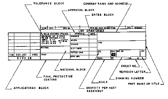
Title Block, Part Number, and Revision Table
A title block contains important information like part name or title, scale, drawing number, drafter name, approver name and company name etc. An example image is given below:
Layers, Line Types, and Color Codes for Clarity
There are several functions to distinguish details in a CAD drawing. As an example, dashed lines may be used for construction only while a solid line represents a geometric edge of a parts. Different colors are used to distinguish different features for instance an orange color might represent chamfer while the part color is yellow.
Dimensions, Tolerances, and GD&T Symbols
Dimensions the size of a feature. The units need to be clearly marked and consistent. Tolerances define the acceptable variation in dimensions.
Popular CAD Drawing File Formats
Choosing the correct file formats for CAD drawings is crucial. It allows for ease of designing and modification. CAD drawings should be saved in a format that is easy to transfer across various systems.
When to Use DWG vs. DXF-2D
.DWG is the standard file format of AutoCAD. Files saved in .DWG can be imported in many different CAD software. .DXF is used for data exchange, especially for 2D vector-based files.
When PDFis Better
PDF file format gives the ease of opening it in almost every computer program. Even smart phones are enabled to view and edit PDF files. It allows CAD drawings to be printed without the fear for unintended modification. It is best for review, printing, or approval by clients or shop-floor teams without CAD software.
When to Use STEP & IGES
Nowadays, .STEP file format is considered as the standard file format for data exchange. 3D annotated models can be shared with ease to CNC software. .IGES is a bit old and less reliable for complex geometries.
How to Convert Stl to Step?
.STL is an also contains meshed parts. Conversion to .STEP might involve specialized CAD and CAM software like Fusion 360 or repair tools of SolidWorks.
What Is A Better CAD Drawing? -Standards
CAD drawings compliant with recognized standards helps to minimize errors. It also makes interpretation of CAD drawings easy. International bodies like ISO, JIS, ASME, DN etc have developed their own standards for organizing engineering drawings.
Standards: ISO 128 &ASME Y14.5 Rules
|
Standard |
Region |
Use |
|
ISO 128 |
Global |
General drawing rules |
|
ASME Y14.5 |
USA |
GD&T |
|
JIS B 0001 |
Japan |
Mechanical drafting |
|
BS 8888 |
UK |
ISO-aligned tech drawing |
Mechanical vs. Electrical vs. Architectural Drafting Conventions
|
Discipline |
Conventions |
|
Mechanical |
Focuses on precise dimensions, tolerances, GD&T and section views |
|
Electrical |
Circuit symbols, wiring diagrams, signal paths |
|
Architectural |
Floor plans, elevations, building codes, layout plans |
From CAD Drawing to CNC Code
The full benefits of a well designed CAD drawing can be reaped after it is exported as a set of instruction into a CNC to do actual manufacturing. This makes manufacturing accurate, precise, consistent, repeatable and automated. However, this involves various steps.
Importing 2D Geometry into CAM Software
A 2D CAD drawing saved in common file formats like .DWG can be imported into a CAM software. The CAM then converts it into a CNC machine readable language like G-Codes. Here’s a quick method of importing .DWG file into Fusion 360 CAM:
Validating Toolpaths Against Drawing Tolerances
A proper validation is needed for flawless manufacturing. The capabilities of the tools should be identified. For example, specialized tools for operations like cutting and drilling etc. should be used. The feature dimensions should match that of the tool. As an example, the tool radius should comply with the fillet radius and so on.
Common Pitfalls & Tips
- Inside Corner Radii: Avoid sharp corners.
- Clearance Holes: Hole size should match the fastener dimensions.
- Layer Mishaps: Layers should not overlap. It might lead to misinterpretation.
Can I Do The Drawing in Cloud & Collaborative?
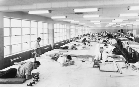
Cloud interface brings a lot of ease in making, modifying and presenting CAD drawings to the design team and clients. It makes a collaborative teamwork environment. Data remains secure against piracy and clients can give feedback timely. In contrast to it collaboration was very laborious before the advent of cloud interface. As example of teamwork without cloud is shown in the image above.
Real-Time Mark-Ups and Version Control
Design team can access the CAD files instantly. They can modify drawings and give feedbacks. Since data is stored on a single computer, it remains invulnerable to corruption caused by saving on multiple versions.
Secure Sharing with Suppliers and Contractors
A big advantage of cloud sharing is that it can be viewed by suppliers and contractors in the real time. They are able to view the CAD design in a real time and ask to incorporate changes wherever needed. Feedback becomes timely. Thus reiterations are minimized.
IP Protection: Watermarks and View-Only Links
The actual file remains on the cloud server. Thus, clients can open it in view-only mode until download is disabled. Even if some images are downloaded, they are protected by watermarks.
Model-Based Definition (MBD) vs. Traditional Drawings
In contrast to traditional drawings Model-Based Definition (MBD) embeds all the necessary information like dimensions, GD&T and tolerances directly into the CAD model. It reduces a lot of paperwork and makes interpretation easy for everyone.
3D PDF and PMI Annotations Explained
3D PDFs include interactive models with Product Manufacturing Information. It replaces static prints with rich and clickable data.
When You Still Need a Lightweight 2D Print
Giving concise information on a 2D print is better when client requires a DXF or PDF. Printed handouts act as a quick reference on shop floors. Also, printed drawings can be checked without the need of a computer and a CAD software.
Transition Strategy: Hybrid Docs for Inspection
A good transition strategy is to use MBD for internal teams and provide simplified 2D drawings alongside 3D models for external QA workflows.
Conclusion
CAD drawings bring a lot of easiness in terms of creation, modification, data transfer and interpretation. CAD opens the way of automation in manufacturing. A CAD file can be processed into a CAM software which then helps a CNC to manufacture products with automation, consistency and repeatability, The incorporation of cloud interface allows for real time access to CAD to all team members and clients. In contrast to it, hand drawn engineering drawings were laborious, time consuming and difficult to interpret.
FAQs
Which CAD software is beginner-friendly for 2D drafting?
AutoCAD LT, FreeCAD and Fusion 360 (Sketch Mode) are considered user friendly for beginners.
Are CAD drawings more accurate than hand sketches?
Definitely. It is because tolerances are very minimum, often down to a fraction of a milli meter. Dimensioning and annotation is computer generated. Hence it minimizes human error.
Can a CAD drawing be used directly for 3D printing?
A CAD drawing usually needs to be processed in a CAM software. It converts the CAD into machine readable instructions for manufacturing operations.
 Overmolding Guide: Process, Materials, Machining Solutions