Tel/WeChat:
  Email:


 Home
HomeCNC G76 Threading Cycle: Programming Guide

 Published:Sep 29,2026
Maintaining consistency in the quality of threads that need multiple passes is often difficult. Even in CNC, differences in programming setups for each pass can ruin quality and consistency. G76 threading cycle provides this solution. It is simpler to program and after that automatic until the thread is finished. Let's dive deep into this topic.
What Is the G76 Threading Cycle?
G76 is a multi-pass threading cycle used on CNC lathes. Like other G Codes, G76 is programmable. Depending on the syntax, parameters like thread pitch, depth, cutting length, tolerances, and infeed strategy can be defined. Since the G76 threading cycle divides the operation into several passes, cutting force on the threading insert is reduced. The quality of threads produced is also superior. Fanuc, Haas, Siemens, and Mitsubishi have different syntax and parameter arrangements.
When Should You Use a G76 Threading Cycle?
G76 threading cycle is generally preferred in situations where a single pass poses difficulty in producing threads. So, rather than manually programming each pass, parameters are set in the G76 threading cycle. G76 G-code automatically calculates and adjusts the subsequent passes. In addition to simplification in programming, the G76 threading cycle ensures repeatability. G76 threading cycle is particularly useful for deep threads, large-diameter threads, fine-pitch threads, difficult-to-machine materials, and special thread profiles.
How to Set G76 Threading Cycle Parameters?
Setting threading parameters is easy in G76 G code. It requires only a few values such as pitch, diameter, initial cut depth, tool angle, etc. Most of the values are extracted from the engineering drawings. Some of the values are calculated from standard formulae.
Common G76 Threading Cycle Formats
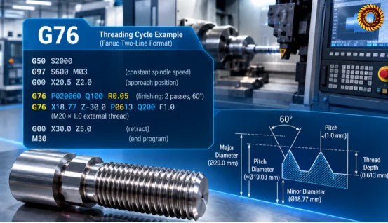
Commonly, the G76 G-code is found in two types of formats. It can be a two-line or a one-line format. Latest machines use a 2-line format, where the first block indicates G76 threading cycle parameters. The 2nd block shows thread geometry and cutting conditions. An example of this syntax is shown here:
G76 P(m)(r)(a) Q(min) R(fin);
G76 X(final) Z(end) R(taper) P(height) Q(first) F(pitch)
One-line format is not universal. It was used by old machines. So, the choice depends on the controller. The engineers should understand all parameters of G76 thread cycle from this table:
|
Parameter |
Definition |
|---|---|
|
P(m)(r)(a) |
6-digit combined parameterm: Finish cutting passesr: Thread lead-out lengtha: Thread form angle |
|
Q(min) |
Minimum cutting depth (μm) |
|
R(fin) |
Finish stock allowance (radius) |
|
X(final) |
Final thread diameter at end point |
|
Z(end) |
Z coordinate of thread end |
|
R(taper) |
Radial taper offset; R=0 for cylindrical thread |
|
P(height) |
Total thread height (μm, radius measurement) |
|
Q(first) |
Depth of the first rough cut (μm) |
|
F(pitch) |
Thread pitch |
Parameters from Drawings
An engineering drawing defines values for thread geometry and dimensions. However, this information should be in a CNC-readable language. So, major diameter, pitch, thread length, thread direction, thread form, and tolerance class are extracted from the drawings directly. These values are then put into the G76 G-code according to its syntax.
Calculate X and P Parameters
Calculate Thread Height
Take an example of an M20 x 1.5 threading profile. Here, if the ISO standard is adopted, the thread height would be calculated as:
h = 0.61343P
For M20 x 1.5:
h = 1.5 x 0.61343
h= 0.92
In the G76 G code format, “P920” in the 2nd block would represent a thread height of 0.92 mm.
But this calculation would vary from one program to another. So, the control manual provided by the manufacturer should be consulted.
Calculate Final X Diameter
For calculating minor diameter, the following formula is used:
X=Dminor = Dmajor−2h
If we again consider the example of M20 x 1.5 threads, the X diameter would be:
X=D minor = 20 - (2 x 0.92) = 18.16mm
Select G76 Cutting Parameters
- First-Cut Depth: Q in the Second G76 Block
The numbers after Q in the Second G76 block represent the first cut depth. As an example, Q200 means 0.2mm.
- Minimum Cutting Depth: Q in the First G76 Block
This Q value is different from the above. It is in the first block. Here, Q100 would mean 0.1mm and so on.
- Finishing Allowance: R in the First G76 Block
Finishing allowance means that small amount of material is left for finishing. As an example, R0.05 means that 0.05mm is left radially.
- Chamfer Amount: Middle Two Digits of P
It determines the pull out and tool disengagement. If the G code as in our previous example is used, in the sequence of “P020060”, “00” indicates zero chamfer.
- Tool Angle: Last Two Digits of Pin the first G76 block
Same as above, in the, in the sequence of “P020060”, “60” indicates a 60-degree tool angle.
How Does the G76 Threading Cycle Work?
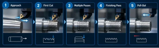
G76 threading cycle does a lot of things automatically in the multi-pass sequence. Just a few parameters in the G76 G code need definition. It then calculates others on its own. Let's take a glance at some of these features.
Multi-Pass Thread Cutting
The main highlight of the G76 threading cycle is its multi-pass cutting strategy. While values for cutting parameters are entered, the program automatically divides the workload. After the engineer enters the following G76 parameters:
G76 P(m)(r)(a) Q(min) R(fin);
G76 X(final) Z(end) R(taper) P(height) Q(first) F(pitch)
The CNC lathe will automatically determine how many passes are required and how deep each pass should be.
Thread Infeed Method
The thread infeed method is defined in the G76 G-code. It determines how the tool insert enters the workpiece. G76 supports 3 infeed strategies including:
- Modified Flank Infeed
- Radial Infeed
- Alternating Flank
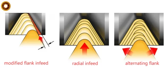
Modified flank infeed is the default strategy for G76 thread cycle.
Finishing Passes
As mentioned in the previous section, finishing allowance can be specified in the G76 G code. Leaving a small amount of material for finishing helps in attaining the correct tolerance class in finishing passes. It ensures proper fitting of mating parts in the assembly.
For example:
G76 P020060 Q100 R0.05
G76 X18.77 Z-30.0 P0613 Q200 F1.0
In this example, the “02”of P020060 means 2 finishing passes. And R0.05 means finish allowance.
Thread Pull-Out
The tool should leave the thread groove without damaging the thread at the end of the thread cut. The Lathe G76 threading cycle defines thread lead-out inside the P parameter. Read this example:
G76 P(m)(r)(a)→P021060
In this example, the r is equal to 10, which means lead-out length. When the tool reaches the thread end on Z axis (along workpiece length), it does spindle-synchronized tapered retract set by r in P. After retraction, X axis (controls workpiece diameter) and Z axis quickly go back to start position to prepare the next cut.
G76 Programming: External vs Internal Threads
G76 threading cycle has different programming approaches for internal and external threads. Since the movement of the tool is different, it invokes the need for different programming values. The calculation of final X diameter, the infeed method, and the pull-out have differences for internal vs external threads.
Final X Diameter for External and Internal Threads
There are clear differences between the calculation for internal vs external threads. For internal threads, the final X diameter is larger than the bore diameter. On the contrary, in the case of external threads, the final X diameter is smaller than the diameter of the shaft. In both cases, the final value depends on thread height and pitch.
Infeed Direction
In the case of internal threads, the tool cuts inside the bore. It moves progressively outward into the walls. For external threads, the tool cuts on the outside walls and moves progressively inwards towards the centerline.
Pull-Out Differences
Pull-out in the case of external threads it quite straightforward. There is abundant room for the tool to detach and disengage from the workpiece. However, internal holes have a constricted space. So there must be sufficient clearance for the tool to move without interfering with the threaded wall. It means that the r value cannot be too large when machining internal threads because the limited space inside hole, otherwise, the collision occurs.
How G76 Settings Affect Thread Quality
G76 threading cycle settings have a profound impact on thread quality. The CNC control only follows the programming instructions. If the programmed values are optimized, then good thread quality can be expected. On the contrary, if the programmed values are wrong, then certain quality issues in the threaded profile can be expected.
First-Cut Depth(Q on the second G76 line)
The first cut depth should be optimized. If it is too large, then excessive cutting forces can cause chatter marks. They will appear as continuous patterns across the thread profile. Excessive forces can also cause deflection of the tool or the workpiece, especially in deep threads. So, a too-large first cut depth may cause improper thread formation and unstable dimensions.
Minimum Cutting Depth(Q on the first G76 line)
Minimum cutting depth should also be optimized. If it is too large, then there will be excessive cutting forces and their associated problems. If it is too small, it will not form a chip; instead, it will merely rub the surface. In addition to wastage of time, it will form rough marks or smear marks on the thread surface.
Tool Angle(last two digits of P in first G76 line)
Tool angle should match the tool geometry. If wrong angles are chosen, the threads formed would mismatch with the mating components.
For instance:
G76 P(m)(r)(60)
In this example, programmed a=60, the engineers should use a 60° V-thread insert but not 55° insert. Otherwise, the thread profile is wrong.
Pull-Out Amount(middle two digits of P in first G76 line)
This issue is especially important for internal threads. Pull-out should be smooth. If pull-out is abrupt, then the threaded profile would remain incomplete at the end. If pull-out is too slow, then burr may form at the thread end.
G76 vs G92 vs G32: Which Threading Method Should You Use?
In addition to G76, G92 and G32 are also G codes for programming threading cycles. While G76 is multi-pass and automatic, G92 requires manual programming for each pass. G32 is more commonly used for customized threads that need synchronized programming for each step. The tables below compare G76 with G92 and G32.
G76 vs G92
|
Feature |
G76 |
G92 |
|---|---|---|
|
Method |
Multi - pass cycle |
Simple threading cycle |
|
Passes |
Automatically calculated |
manually programmed |
|
Programming |
Shorter |
Longer |
|
Cut Depth |
Automatic |
Controlled per pass |
|
Finishing |
built into cycle |
Programmed separately |
|
Flexibility |
Lower |
Higher |
|
Benefit |
Fast and repeatable |
Simpler and direct control |
G76 vs G32
|
Feature |
G76 |
G32 |
|---|---|---|
|
Method |
Multi - pass cycle |
Synchronized threading |
|
Passes |
Automatic |
Manual |
|
Programming |
Short |
long |
|
Tool Path |
Automatic |
Programmer -controlled |
|
Flexibility |
Lower |
Higher |
|
Benefit |
fast and repeatable |
Precise control |
Advantages of the G76 Threading Cycle
The advantages of the G76 threading cycle are numerous. It is commonly used in custom thread CNC machining because it is simple to program and is repeatable in quality. For multi-pass threading cycles, everything is automatic for intermediate passes.
Simplified Programming
G76 threading cycle is comparatively simpler than other G Codes for multi-pass threading operations. Only a few parameters, such as thread depth, first-cut depth, minimum cutting depth, finishing allowance, pitch, and final diameter, need to be defined. The algorithm itself calculates the parameters for intermediate passes.
Consistent Quality of Threads
Since programming is simple and that too is defined only for the first time, chances of human error are less. For every identical piece, the same G76-programmed G-code is used. It produces identical thread profiles each time. This consistency ensures proper fitting of mating parts.
Suitable for Multiple Thread Types
CNC G76 threading cycle supports cylindrical and tapered threads. It can also machine regular trapezoidal and square threads.
Limitations of G76 Threading Cycle
Not Suitable for Complex Threads
G76 threading cycle is highly automated, so the toolpath is auto-generated. The engineer can't manully freely set some values. Therefore, G76 is not suitable for machining complex threads such as variable-pitch or asymmetric profiles. G32 is better for machining complex or irregular threads.
Not Suitable for Very Short Threads
Short threads usually provide limited space for tool movement. The restricted space makes transitioning from threaded to non-threaded portion difficult. Tool pull-out may become inadequate. In these situations, other G codes like G92 may be used.
Difficult to Machine Threads with No Run-Out Space
Threading profiles with no run-out space are difficult to machine with the G76 threading cycle. G76 requires clearance for tool disengagement. For example, if a thread is required adjacent to the shoulder, pull-out would be abrupt. Either the thread would be left incomplete, or the tool would collide.
What Are the Key Thread Features to Inspect When Using G76?
Good quality threads will always mate smoothly. Bad quality will cause issues with fitting. Therefore, the strict quality inspection of threads is important. The engineers should check the quality of threads from:
- Thread Profile: Check whether the thread profile is complete or distort.
- Thread Pitch: Check pitch accuracy, avoiding pitch deviation caused by spindle synchronization errors.
- Major / Minor Diameter: Make sure the major and minor diameters are right to ensure the proper assembly.
- Surface Finish: Visual inspection can reveal the actual surface condition. Look for chatter marks, smears, build-up on edges, and burrs.
- Thread pull-out: Thread pull-out can be checked visually. Check whether threads are complete or not. Look for burr and improper transitions between threaded and unthreaded portions.
Conclusion
G76 is a multi-pass threading cycle used for creating threads that cannot be completed in a single pass. It requires the input of a few threading parameters. The controller manages the production of threads in the subsequent cycles automatically. Remember that G32 instead of G76 is suitable for creating complex threads. Engineers should choose G76 properly according to the thread length, profile, and tolerance requirements.
FAQ
What is the G76 cycle on a FANUC machine?
On a FANUC machine, it is a multi-pass threading cycle capable of producing internal and external threads.
How to use G76 threading cycle?
A G-code needs to be programmed. Datums are to be set. Parameters are to be defined. The rest is up to the CNC.
How do I program G76 on a Haas lathe?
Check the G-code syntax in the Haas lathe manual. Calculate the initial parameters. Input that data into the G-code programming.
 Why Fretting Wear Occurs and How Precision Machining Mitigates It?