Tel/WeChat:
  Email:
 Home
HomeStraightness vs Flatness in GD&T: Key Differences

 Published:Oct 21,2025
In precision CNC machining, dimensional tolerance is one of the important features and is highly depends on straight and flatness accuracy. These features define shape and size of part. The terms straightness and flatness are used interchangeably but in Geometric dimensioning and tolerance (GD&T), they have their individual definition and functions. This article will help you explore the meaning of straightness and flatness in GD&T and its importance in product design.
What Is Straightness?
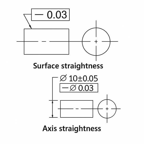
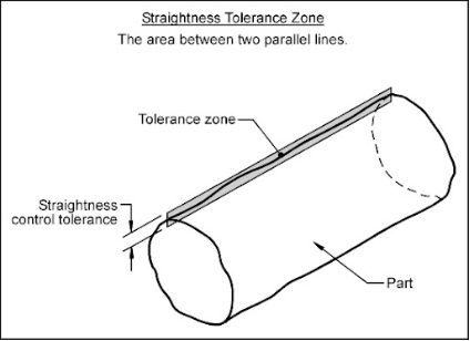
Straightness measurement means the part is linear within a defined tolerance and has no curve or bends. Tolerance zone is normally cylindrical for axis straightness. and straightness is represented by a single horizontal line in drawing.
Surface Straightness
Surface straightness is the control applied to line element that is present on a surface. Straightness definition engineering is that a specific line is straight on a surface on a given tolerance.
Where Straightness Applies on Drawings
Straightness GD&T symbol is (|--|) and is used for a feature control frame on an engineering drawing. The feature control frame shows the feature that is being controlled like edge, a center point, or a cylindrical surface.
What Is Flatness?
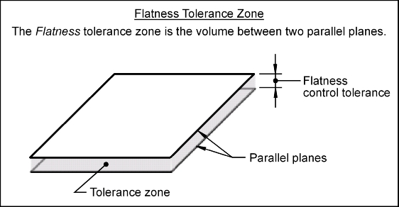
Flatness is a "form control" that tells how flat a surface must be without reference to any datums. It is the 3D equivalent of straightness in GD&T and controls the entire surface, not just a line.
Flatness Tolerance Zone
Its tolerance zone is a 3D space defined by two parallel planes, with the entire surface required to be in this zone. For example, a heat sink base. Its flatness symbols show that all the points on the base are within the specified zone and have uniform contact with heating and cooling system.
Flatness Callout on Drawings
The flatness GD&T symbol is a horizontal line within a rectangle. The flatness symbol has a tolerance value of 0.05 in a drawing.
Flatness vs Surface Finish
Flatness is a macro-level control to define the overall form of a single surface. It confirms that control lies between two parallel planes. While surface finish is a micro-level control to define the microscopic smoothness and texture of that surface.
Flatness vs Parallelism
Flatness has macro-level control overall form of single surface. while parallelism has macro-level control related between two surfaces. For example, flatness is a single surface within a specific tolerance band and parallelism is top and bottom surfaces on a same distant apart across the entire area.
Straightness vs Flatness: Key Differences
This section will further specify the difference in features in flatness and straightness.
1.Tolerance Zone Shape
The tolerance zone shape for straightness is cylindrical for an axis or a planar zone for a surface. And for flatness it is two parallel planes.
2.Where It Applies on a Part
The straightness measurement is for a shaft's axis that must be straight to fit into a bearing, or a long, slender part without bending. Flatness is used on sealing surface on an engine block that must be flat to prevent leaks.
3.What Each Control Limits
Straightness has a control form of a single line (axis or across a surface). flatness has control form of an entire surface.
4.Feature Types
Both have different feature types same as the control form or tolerance zone shape.
When to Specify Straightness vs Flatness
Straightness is specified for rotating parts, sliding fits, and for dominant length or axis of parts. Flatness is specified for bolted joints, mating surfaces, and features with uniform contact or a seal.
How to Measure Straightness and Flatness
This section will specify the testing methods and tools for straightness and flatness.
How to Test for straightness?
Straightness can be measured with physical tools and with some advanced methods like laser system or coordinate measuring machine (CMM) for precise results.
Measuring Tools
There are many tools to measure straightness like:
- Straightedge and feeler gauge:placed on surface to measure the gaps between the feeler gauge and straightedge. Large gaps mean less straightness.
- Dial indicator:to measure the distance of surface movement relative to a fixed point.
- Laser beam system:laser projects a straight reference line, and sensors detect the deviation.
- Height gauge:measures the difference in height at different points along a line.
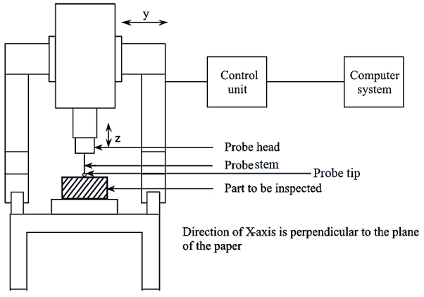
- Coordinate Measuring Machine (CMM):uses a probe to measure multiple points on a surface and measures straightness digitally.
Measuring Methods
The methods of measuring for straightness are:
- Direct measurement:through straightedge, dial indicator or feeler gauge.
- Roller method:Rolling the object on a flat surface to check for wobbling.
- Laser scanning:uses laser beam to detect the position of the beam's reflection.
- CMM measurement:uses CMM probe to take a series of measurements.
How to Measure Flatness
The core principle to measure flatness is to define the minimum distance between two parallel planes within the entire surface.
Measuring Tools
The measuring tools to measure flatness are:
- Height Gauge:uses dial indicator to measure the vertical deviation of a surface.
- Feeler gauges:a thin strip set to measure the distance between the surface.
- Optical flat: a transparent glass creates interference patterns between the two surfaces to show surface's flatness.
- Laser scanner: laser sans millions of points on a surface to create a highly detailed 3D map for flatness analysis.
Measuring Methods
The measuring methods are:
- Height Gauge and Dial Indicator:to measure difference between the highest and lowest reading is the flatness.
- Coordinate Measuring Machine (CMM): to measure the flatness is the perpendicular distance between these two planes.
- Optical Flat: if shows curved or unevenly spaced lines means the surface is not flat.
Tips for Straightness and Flatness in GD&T
There are few tips to ensure the straightness and flatness in GD&T.
Setting Functional Tolerances
For a shaft fit into a hole, use Maximum Material Condition (MMC) modifier on both the shaft and the hole. This confirms the correct part assembly. For a seal, matting surface must have a close fit. And for boss pin on an engine housing, use an axis straightness tolerance with MMC for correct alignment.
Using MMC for Axis Straightness
MMC modifier on axis straightness reduces the size from MMC toward Least Material Condition (LMC). The bonus tolerance helps the feature to be less straight if it is smaller and has clearance for motion.
Notes for Long/Thin Parts
For thin-walled parts, supporting at the ends maintains its intended geometry. For its inspection, measure deviations using a height gauge or dial indicator.
Straightness vs Flatness Examples
The examples of straightness are the axis of a motor shaft and for flatness these are sealing faces on a gasket. The straightness vs flatness examples are:
Shafts, Pins, and Spindles
The moto shaft axis must be straight to minimize vibration and have smooth rotation. Dowel pins and spindles must be straight for proper insertion into the holes.
Rails, Ways, and Extrusions
The guide rails, long extrusion or lengthwise elements must be straight for consistent movement or alignment.
Sealing Faces and Housing Pads
A gasket surface on a housing should have flatness to make seal and prevent leaks under pressure.
Conclusion
Straightness controls the form of a line or axis. And flatness controls the form of an entire surface. Straightness has two parallel lines to define its tolerance zone suitable for shafts or edges, and flatness has two parallel planes for its tolerance zone, required for mating or sealing surfaces. Straightness and flatness symbol are different in engineering drawing.
FAQs
What is the difference between flatness and perpendicularity?
Flatness measures the level of single surface is level and present between two parallel planes. Perpendicularity is a relationship between two intersections at a 90◦angle.
What is parallelism in GD&T?
It is a geometric tolerance to control the orientation of a surface or an axis parallel to a datum feature.
How to read straightness tolerance?
Imagine a "tolerance zone" of two parallel lines with the distance between of specified tolerance value. Any measured line on the axis must fall completely within this zone.
 Ceramic CNC Machining: Materials, Processes, and Alternatives