Tel/WeChat:
  Email:
 Home
HomeHow to Prepare a DXF File for Machining? -Complete Guide

 Published:Jun 07,2025
A poor DXF file For machining forces an engineer to answer emails instead of moving a project forward. The steps below break the task into problems, fixes, and clear suggestions.
Before Making DXF File: Essential Machining Parameters
Lock these parameters before touching the CAD model; they drive every later decision, from layer naming to final pricing.
Material and Thickness
Select alloy grade and sheet gauge up front. A 3 mm 6061 sheet cuts with far less power than 10 mm 304 stainless. The CAM post adjusts feed, speed, and pierce count based on this single choice.
Sets Kerf and Minimum Feature Size
Water-jet, laser, plasma, and router each leave a different kerf. Plan slots, tabs, and vent holes to stay above that value; otherwise they wash out on the shop floor.
| Process | Typical Kerf (mm) | Smallest Hole Ø (mm) |
|---|---|---|
| Fiber laser (≤ 4 kW) | 0.10 – 0.15 | 1.0 × material thickness |
| CO₂ laser | 0.15 – 0.25 | 1.2 × thickness |
| Water-jet | 0.25 – 0.40 | 1.5 × thickness |
| Router (Ø3 mm tool) | 3.0 (tool Ø) | 3.0 |
Surface Finish and Post-Process Notes
If anodizing, powder-coating, or tumbling is required, add a 0.05 – 0.10 mm stock allowance in the outline. List the finish in a note so the vendor prices it without follow-up emails.
Before Exporting Your DXF File: Diagnose Some Issues
Before saving as DXF, run two quick checks inside CAD to catch hidden geometry and misplaced entities.
1.Run CAD audit tools
Most CAD packages include “Audit” or “Purge.” Run them; fix what the report shows. If the report lists zero errors, continue to the next check on the DXF file For machining.
2.Zoom-extents check
After deleting obvious clutter, zoom out. If the part vanishes to a pixel, stray geometry sits far from origin—delete it. Keeping geometry near X=0, Y=0 helps CAM center stock automatically.
Step-by-Step Preparation Workflow for Your DXF File
The seven steps below build on one another; follow them in order for a shop-ready file.
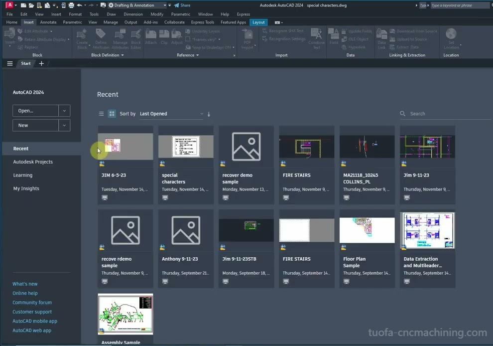
1. Start from the authoritative CAD drawing
Open the original solid model, verify the CAD drawings, or refer to the authoritative engineering drawing. Always export the DXF file For machining from the master document.
2. Set correct units and scale
Confirm the part dimension in the title block. If the solid measures 100 mm, the DXF file For machining outline must also read 100 mm—never 3.937 in. Scrub the file now to prepare for an instant quote online later.
3. Flatten to 2D, then project critical views
Machining centers use X-Y cutting paths. Create top, bottom, or side views only as needed. Avoid isometric projections that create unwanted diagonal segments.
4. Build a machining-friendly layer structure
| Recommended Layer | RGB Color | Purpose |
|---|---|---|
| CUT_OUTLINE | 1,0,0 | Through cuts |
| ENGRAVE_TEXT | 0,0,255 | 0.1 mm depth marking |
| DRILL_Ø6.00 | 0,255,0 | Drill toolpath |
| ETCH_GUIDE | 255,0,255 | Non-cut reference |
Shops import layer names into CAM automatically. Consistent naming prevents the classic midnight call: “Should the blue lines be cut or scribed?”
5. Remove non-machining elements
Delete title blocks, borders, center marks, and dimension arrows. Keep only geometry that drives the tool. Less clutter equals lighter files and fewer parsing errors.
6. Convert splines to polylines
CNC controllers interpret arcs better than splines. Use a tolerance of 0.05 mm for laser or 0.10 mm for plasma. Smaller tolerances inflate vertex count and file size without better accuracy.
7. Save to DXF R14 or 2013
These versions balance entity support and file size. They load in most CAM systems without plugins. Newer formats often embed proxies that confuse older post-processors.
Verify Geometry and Tolerances
The following checks confirm that what you exported is exactly what the machine will cut.
Closed polylines rule
Each contour must start and end at the same coordinate. Use “PEDIT → Close” or equivalent. CAM software treats an open contour as safe travel, not a cut.
Minimal vertex count
A 50 mm circle does not need 500 points. Excess vertices slow the machine buffer. Aim for 36 segments or fewer. Most lasers interpolate arcs smoother than the input, so fewer vertices equal smoother movement.
Annotate only critical tolerances
Place ±0.05 mm next to holes that locate bearings. Skip general notes; the DXF file For machining drives the cut, not the print. Adding too many tolerances raises the quote because the shop must measure them all. Most CAD drawings list a general tolerance block—use it, do not repeat every size.
Before Sending Your DXF File: Export Checklist
Use this short list as the final gate before attaching the file to an email or portal upload.
| Item | Pass/Fail |
|---|---|
| Units confirmed (mm/in) | |
| Origin at lower-left corner of part | |
| Layers follow shop spec | |
| File opens in free viewer without error | |
| Size < 5 MB |
Tick every box before attaching the file. The checklist saves one email thread per project—multiply that across a year’s builds for real time savings.
One-Stand TUOFA's CNC Machining Custom Service: From File to Production
For many people, a one-stop customization → production process is more convenient. That's why TUOFA CNC Precision Custom Machining stands out.
Start by uploading a simple CAD model or 2D drawing (in DXF, STEP, STL, or IGES format; or a photo of the product), and the professional TUOFA engineering team will respond quickly to your project - usually within 4-5 hours - the clearer the requirements, the faster the accurate quotation response.
Contact us now to start your project~
Try Tuofa Now!Get A Quick Quote Now! -Tuofa Engineer Support Team |
Instant Quote Online! |
Conclusion
An engineer who masters the checklist above ships clean data on the first try, secures tighter lead times, and protects budget. Keep the DXF file For machining simple, layered, and verified. Combine the file with clear CAD drawings and a labeled PDF to prepare for an instant quote online without back-and-forth. Let the data speak, and let the machine run.
FAQs
Engineers ask these three questions on nearly every project; the quick answers below clear them up.
Is a DXF enough, or do I need the 3D model?
For flat parts, the DXF file For machining plus material callout is enough. For milled pockets or counterbores, include the STEP file so CAM can generate toolpath Z-moves.
What CAD version should I export?
Stick to AutoCAD R14 or 2013 unless the shop specifies otherwise. Few systems need the newer 2024 entities for simple outlines.
How dense should the polyline segmentation be?
Maintain chordal error under 0.05 mm for lasers; routers can accept 0.1 mm. Excess precision inflates file size but rarely improves cut quality.
 Mechanical Joint vs. Flange: Choosing the Right Connection for Your Project