Tel/WeChat:
  Email:
 Home
HomeWhat Is Finite Element Analysis (FEA)? How Does FEA Works?

 Published:Oct 15,2025
Finite Element Analysis (FEA) is a mathematical calculation and models that engineers use in their analysis process. It creates a computer simulation that predicts the material's behavior. There is a lot more about FEA if you want to create any design for your product before giving it to the CNC machining expert. This article will help you to understand all the essential details of FEA. So, let's get started!
What Is Finite Element Analysis (FEA)?
For designers in the product development process, FEA is an online prototyping tool that simulates the design's behavior under real-world conditions. It predicts potential problems, optimizes performance, and avoids costly manufacturing errors by creating physical testing to the digital space.
What Does FEA Stand for?
FEA stands for Finite Element Analysis, an online tool in the design process.
FEA's Purpose in Engineering
FEA has main purpose of helping engineers to identify design flaws and improve products at earlier development stages. Its main functions are structural analysis, thermal analysis, dynamic and vibration analysis and design optimization.
FEA vs FEM vs Simulation Scope
These terms are related but have different purposes.
Finite element method (FEM) is a mathematical algorithm and breaks object into smaller mesh called “finite element”. Then it applied mathematical equation to each element and solve them to analyses their behavior.
Finite element analysis is the application of FEM. It is the process of setting up, running and interpreting simulation results.
Simulation is a broader term for imitating a real-world process or system. FEA is a type of engineering simulation, and this includes Computational fluid dynamics (CAD) for liquid and gases and Electromagnetic simulation for electromagnetic field.
Is FEM Used in Mechanical Engineering?
Yes, FEM is used in mechanical engineering for stress, strain and deformation analysis, fatigue analysis, thermal analysis, vibration analysis etc.
Relationship of FEA and CNC Machining
FEA improves and refines the entire CNC machining process. The role of FEA in CNC machining starts from the initial design phase to the optimization of machine tool structures. It helps engineers to virtually simulate and analyze the effects of physical forces like stress, heat, and vibration on parts and machinery.
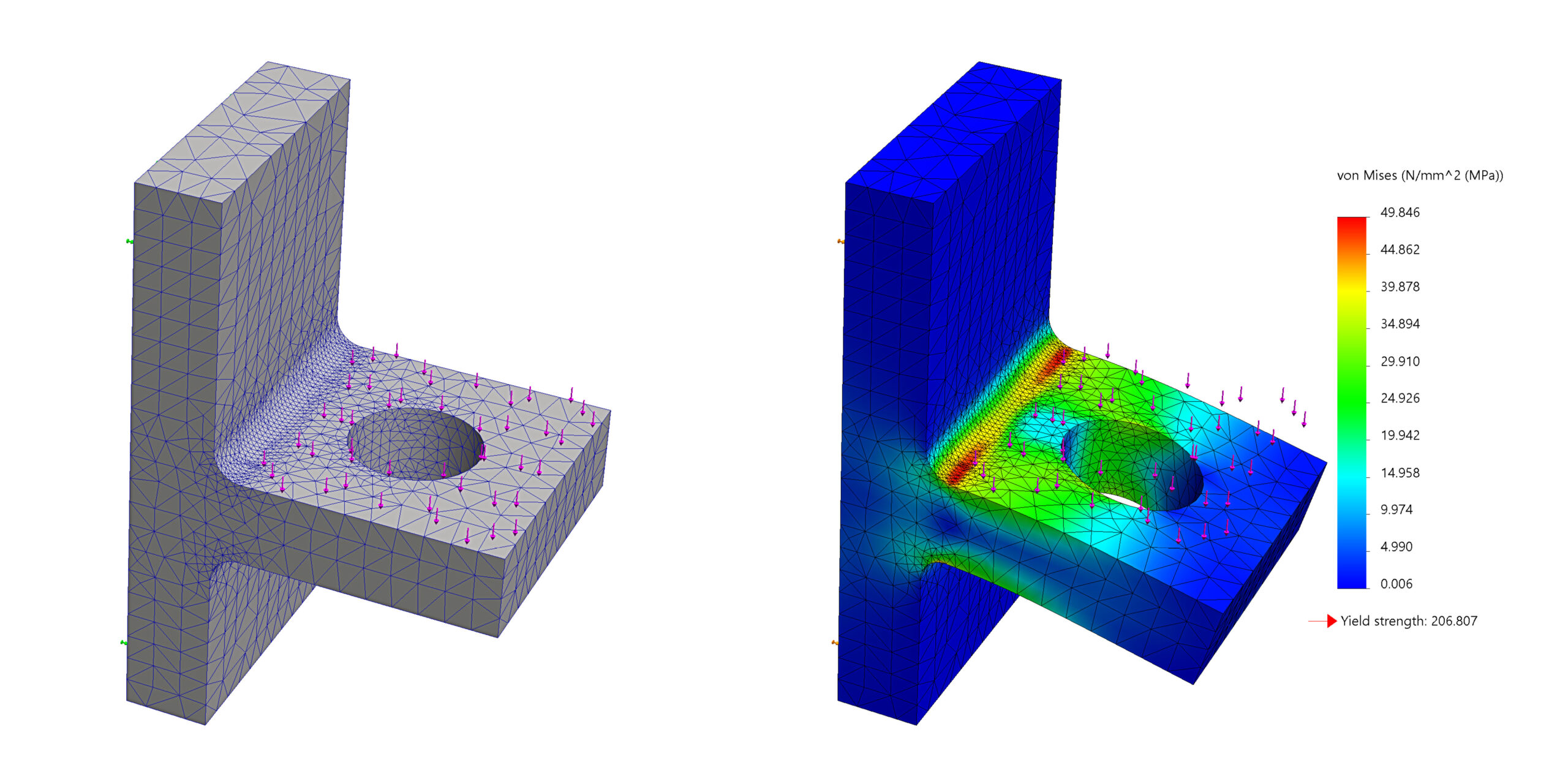
How FEA Works: From Model Setup to Results
FEA involves Pre-processing, solving and post-processing steps to get the optimized results of simulation.
1.FEA Pre-processing Overview
This step is the foundation of FEA. Model is prepared by CAD geometry, and each element is divided into small mesh. Boundary conditions like loads, constraints, and initial conditions are applied to the meshes.
2.Solver Options and Settings
"Solver" is the main part of the FEA process. It takes all the pre-processed data and performs the complex mathematical calculations to analyses the object's behavior. And depending on the analysis, engineers choose different simulation settings like static analysis, dynamic analysis, modal analysis or non-linear analysis.
3.FEA Post-Processing Overview
This is the final stage and all the raw data from analysis is interpreted into a visual format. Quantitative analysis like maximum stress, strain, or displacement values is done for validation and reposting the results of finite element analysis software for structural engineering.
Types of FEA Analyses and When to Use Them
There are different types of FEA and depending on the requirement, each analysis is selected.
1.Linear Static Stress
It is common type of FEA which is computationally efficient. It is done on early designs stage for rapid structural optimization, material selection and feasibility. It also determines the safety factor of a design under a constant load.
2.Modal and Harmonic Vibration
These are important to understand a structure's dynamic behavior. Modal and harmonic analysis are used to prevent resonances in designs and to evaluate the vibration response of machine part like gears.
3.Transient Dynamic and Shock
Transient dynamic determines the time-dependent response of a structure like stress, strain when inertial or damping effects are important. Shock analysis is a form of transient dynamic analysis which analyzes effect of a sudden, high-intensity load like impact or collision.
4.Thermal (Steady-state and Transient)
Thermal analysis talks about the heat transfer within a structure. It analyzes the temperature fluctuations of an engine part from startup to a steady operating state.
5.Nonlinear (Material, Geometry, Contact)
It is a complex computationally intensive analysis. This is used when the relationship between force and displacement is not linear. This is done in rubber or plastics and in the structures with large deformations.
6.Fatigue and Durability
This predicts the lifespan of a component subjected to repeated or cyclic loading like crankshaft or suspension arm.
Finite Element Analysis Examples
FEA is done for a wide range of materials in different industries for different purposes. The finite element analysis examples are:
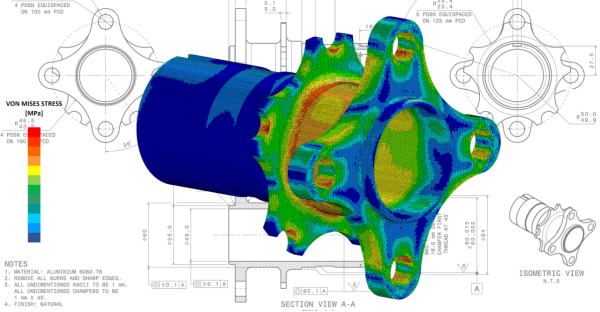
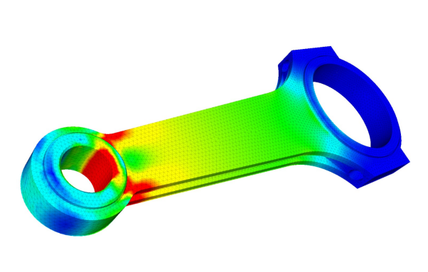
Automotive Parts Engineering
FEA is important for developing durable, safe and lightweight automobile parts. It is carried out for crashworthiness analysis, engine connecting rods. Brake pad thermal analysis, vibration and noise reduction and for chassis and suspension optimization.
Aerospace Parts Engineering
FEA in aerospace helps to ensure structural integrity, weight optimization and fatigue life prediction under extreme conditions. It is done on aircraft wings and fuselage, Jet engine rotors, and for landing gear integrity.
Robotics & Automation Parts
FEA is done on robotics parts to make sure they are stiff, lightweight, and durable to do their functional loads. It is done for robotic arm design, structural optimization, component durability, and for flexible mechanism analysis.
Custom Parts Machining
FEA helps to analyze the performance of custom parts and especially complex geometry parts. It is used for machining process simulation, tools and die analysis and custom wire baskets etc. It is ideal for complex shapes parts like biomedical devices, civil engineering structures and turbine housing assembly etc.
FEA for CNC-Machined Metal Parts
FEA on machined part helps to detect issues, like deflection, stiffness, residual stresses and structural integrity.
Thin-Wall Metal Parts
Thin-walled structures are weak and less stiff and can be distorted and dimensionally inaccurate during machining. FEA provides a deformation prediction and thermo-mechanical analysis to determine deflection and stiffness.
Fixturing, Clamping, and Residual Stress
Clamping forces and residual stress can introduce deformation in CNC machining. FEA can perform different fixture setups to identify the optimal clamp and support locations. Residual stress analysis and compensation for distortion can also be done with FEA.
Weight Reduction
Weight reduction is important in many industries like aerospace. FEA is an important technique to get optimized geometry and weight. It can perform topological optimization, create generative designs and do design evaluation to check strength and ductility of lightweight material.
What are the Common Software for FEA Analysis
For FEA, common software used and categories in three ways: dedicated FEA programs, CAD-integrated tools, and multipurpose simulation suites.
Popular FEA Tools
The common tools for FEA are:
1.ANSYS
It is a versatile tool with comprehensive features for structural, thermal, fluid dynamics, and electromagnetic analysis. It is best for high-fidelity simulations for complex engineering problems.
2.Abaqus
It is an advanced FEA tool that is mostly used in automotive and aerospace industries. It can perform non-linear analysis and complex multi-physics simulations.
3.SolidWorks
FEA features directly integrated in SolidWorks CAD environment and can perform design validation and analysis of mechanical parts and assemblies.
4.Fusion 360
It is a cloud-based platform for CAD, CAM, and CAE. It has static, thermal, and generative design capabilities and simulation is done on the cloud.
Tips for Using These Tools
To get optimized results of FEA,
- Use simple design model
- Make a free-body diagram
- Use the right type of element
- Know the material properties
- Validate your model
Tips to Avoid Common FEA Errors
Keep these tips in mind to avoid FEA errors:
- Define the contacts correctly
- Do not over-simplify boundary conditions
- Check for non-convergence
- Do not use singular stress points
- Understand the linear analysis limitations.
Advantages and Limitations of FEA Analyses
FEA analysis has a wide range of advantages and a few disadvantages. Some of them are:
Benefits of FEA Analyses
The benefits of FEA Analyses are:
Faster Design Cycles
It speeds up the product development process by reducing the need for time-consuming physical tests.
Fewer Physical Prototypes
FEA eliminates the need for expensive physical prototypes.it saves time and cost for manufacturing and testing.
Early Failure Detection
It identifies potential weaknesses and failure points at designing stage. This saves costs and unexpected project delays.
Limitations of FEA Analyse
Few limitations of FEA analysis are:
- It requires expertise
- It depends on input data
- It has potential for misinterpretation
- Some analysis can be difficult and can only be performed by specialized methods.
Conclusion
FEA is a computational method and simulates the product's behavior in under real-world physical conditions, like stress or heat. It is an important tool in advanced manufacturing to identify the potential weaknesses and can optimize designs virtually before creating final product in CNC Machining.
FEA FAQs
How accurate is FEA for real parts?
FEA is very accurate for real parts and has only 1-5% error chance in physical test results.
Which software is best to start with?
Ansys is the best one to start FEA with.
Can ChatGPT do finite element analysis?
Yes, ChatGPT can do FEA by generating code for FEA libraries. But be careful to ensure the authenticity and validity of the data.
What is FEA and CAD?
CAD is a software to create 2D and 3D digital models of objects. And FEA is a simulation method that uses these CAD models to analyze the object's behavior.
 How to Demagnetize Metal? Something You Must Know