Tel/WeChat:
  Email:
 Home
HomeUnderstanding Pitch Diameter: Design, Manufacturing & Gauging

 Published:Nov 15,2025
Pitch diameter is important to understand for designers and manufacturers for perfect assemblies fitting. It has an important role in optimizing fitting efficiency and their overall performance. This article will give you detailed information about the pitch diameter and its role in industries.
What Is Pitch Diameter?
It is an imaginary diameter of a circle intersecting the threads at a point where the widths of the thread and grove are equal. It is also called an effective diameter. Pitch diameter is a key measurement for designers to have proper fit between two threaded parts, like bolt and nut. Incorrect pitch diameter causes poor engagement, wear, and potential failures in your designs.
Pitch Diameter of Thread
Pitch diameter has equal widths of thread and grooves. It has the largest major diameter from crest, a smaller minor diameter from root and pitch. Pitch is the distance between corresponding points on adjacent threads.
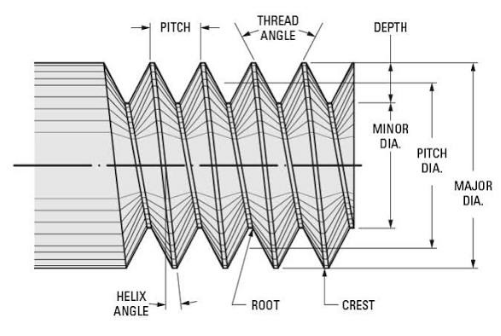
What Is Thread Pitch
It is a distance between a point on one thread and the same point on the next thread. You can measure it parallel to the screw's axis as Threads Per Inch (TPI). If a bolt has "1/2-13", there are 13 TPI.
What Is Depth of Thread
It is a perpendicular distance from the crest of a thread to its root.
What Is PCD in Thread?
Pitch circle diameter (PCD) is an imaginary circle diameter from the centers of the bolt holes like on wheel or flange.
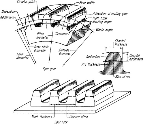
Pitch Diameter of Gears
It is an intermediate measurement from the major and minor diameters. Major is the largest and minor is the smallest distance of the gear’s teeth.
Pitch Diameter vs. Major vs. Minor Diameters
Pitch diameter is an imaginary diameter. It is roughly a center between major and minor diameters. It is often represented by the symbol D or d.
Major diameter is the outer diameter of the gear. It is represented by D or d for the outside diameter or Do.
Minor diameter is the root diameter of the gear teeth. and it is represented by d or Dr for the root diameter.
Pitch Diameter vs. Mean Effective Diameter
Mean effective diameter can be used interchangeably with pitch diameter when you are talking about the threads. It is the diameter where the meshing contact occurs between two parts. Pitch diameter is specifically used for diameter for gears. While the “mean effective diameter" is broader term and you can use it both the threads and the gears.
What Are Thread Standards and Notation
Thread standards specify the dimensions and specifications for interchangeable screws, bolts, and nuts to make them understandable for us. ISO Metric (M) and Unified (UN/UNF/UNEF) are the common standards to define them.
ISO Metric Threads (M)
It is represented with M and the major diameter in millimeters and pitch in millimeters. Like M10 x 1.5. pitch is assumed if not mentioned anywhere.
|
Thread Designation |
Major Diameter (mm) |
Pitch (mm) |
|
M3 |
3 |
0.5 |
|
M6 |
6 |
1.0 |
|
M10 |
10 |
1.5 |
|
M12 |
12 |
1.75 |
|
M16 |
16 |
2.0 |
|
M20 |
20 |
2.5 |
|
M24 |
24 |
3.0 |
Unified Threads (UN/UNF/UNEF)
It is represented as a dash and a number showing the TPI and thread series designation like 1/4-20 UNC bolt has 1.4in diameter and 20TPI. The thread series are Unified National Coarse (UNC), Unified National Fine (UNF) and Unified National Extra Fine (UNEF).
Class of Thread Fit
Class of thread fit are like 1A/1B, 2A/2B, 3A/3B. in this, A is an external thread like bolt, B is internal thread like nut and Fit is the degree of tolerance, higher number showing a tighter fit.
- 1A/1B: For threads with easy assembly.
- 2A/2B: general purpose fasteners.
- 3A/3B: For very close and secure fit
Tolerance Symbols
ISO metric uses a letter code to represent the allowance and tolerance. Lowercase for external and uppercase for internal) and the specific letter shows position of the tolerance zone.
For Unified, the class of fit (1, 2, 3) is the primary tolerance indicator.
Why Pitch Diameter Matters in Parts Design
Pitch diameter is an important parameter in design. It can directly affect the teeth meshing, center distance between gears and control of backlash when considering gears and screw threads.
For Gears System
Pitch diameter helps with proper functioning and optimal performance within a mechanical system of gear.
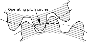
1. Ensuring Proper Meshing
Pitch diameter determines the size of the "contact area" between teeth when gears engage. If this distance of two gears is not properly matched, you cannot mesh them correctly. This can cause inefficient power transmission or can damage the teeth
2. Exact Center Distance
Pitch diameter is directly related to the center distance between two gears. It helps to achieve desired gear ratio by specifying the pitch diameters and calculating the necessary center distance.
3. Controlling Backlash
Backlash is the minor gap between teeth if gears engagement is not proper. The pitch diameter affects the amount of backlash. As the larger pitch diameter generally results in less backlash.
For Screw Threads
Pitch diameter is important to know the thread depth and engagement and lead and rotation.
1. Determine Quality of Fit
The pitch diameter determines the depth of the thread cut and contact area between screw and nut. It is important for proper load transmission and thread strengths of your design
2. Does Pitch Diameter Impact Thread Strength?
Yes, it affects thread strength. Because it helps with proper thread engagement and load distribution. An incorrect pitch diameter causes weak connections, stripped threads, or failure under stress of your fasteners.
Tips for Better DFM (Design for Manufacturing)
Some tips for design of manufacturing (DFM) are:
- Use simple geometry and not use undercuts, deep cavities and sharp internal corners
- Provide clear tool path and do not use long and slender tools
- Use tight tolerance when needed because it can be costly
- Choose material with good machinability and moderate hardness and strength that can affect your tool wear in pitch measuring.
Selecting the Right Fit with Pitch Diameter
The important things to understand when selecting the right fit with pitch diameter are the corresponding tolerance class and its relevance to the desired level of tightness or looseness between the male and female threads for a given application.
Metric Fits
The first letter, like "g" or "h," shows the tolerance class on the external threads. The second letter shows the tolerance class on the internal threads.
Unified Fits
Letter "A" denotes a relatively loose fit, "B" a medium fit, and "C" a tight fit. And the number before letter shows the thread class 2A means classs2 external and Class 2 internal threads.
Selecting a Fit for the Application
Class 1/2/g/G is for loose fits used for easy assembly like adjusting screws or nuts.
Class 3/4/h/H is moderate fit for ease of assembly and proper engagement.
Class 5/6/7/8 is tight fit for better strength and precision.
How to Calculate Basic Pitch Diameter
Pitch diameter is a fundamental measure for both gears and screw threads. It shows the pitch diameter circle where gear teeth mesh is of a standard diameter.
ISO Metric: Basic Relationships
The basic relationship for measuring pitch diameter in ISO metric as:
d2= d - (3√3 × P/8)
which simplifies to
d2= d - 0.866 × P
d2 is basic pitch diameter and d is Major Diameter and P is thread Pitch
Unified: Basic Relationships
In Unified standard, the basic pitch diameter is calculated by subtracting a value based on the thread's pitch from the major diameter.
Calculating Pitch Diameter for Screw Threads
Pitch diameter for screw threads is measure by the formula:
D = M - 0.4330 × P
Where, D is Pitch diameter, M is Major diameter and P is Thread pitch
Calculating Pitch Diameter for Spur Gears
Spur gears can be calculated by using diametral pitch as:
D = N / P
Where, D is Pitch diameter, N is Number of teeth and P is Diametral pitch
Spur gears can be calculated by using module as:
D = N × m
Where, D is Pitch diameter, N is Number of teeth and m is Module
Calculating for Helical Gears
The pitch diameter for helical gears is calculated based on the normal plane.
D = N / Pn
Where, D is Pitch diameter, N is Number of teeth and Pns Normal diametral pitch
How to Measure Pitch Diameter
There are many methods to measure pitch diameter. One of the common methods is:
Three-Wire Method
Three-wire method is also called “3-thread rule”. The pitch diameter of a screw thread is measured by placing three precision wires in the thread valleys and measuring the diameter over the wires. The obtained result is subtracted to calculate the pitch diameter. The formula is:
M = E-0.86603P + 3W
Where, E is pitch diameter, P is pitch, and W is wire diameter.
Wire Size Selection
The ideal wire diameter contacts the thread at the pitch line. It is also known as "best size" wire. It minimizes measurement errors due to variations in the thread angle.
Measurement over Wires Procedure
The procedure to measure is:
- Select an appropriate wire diameter for thread pitch
- Place two wires on top and one below, or vice versa
- Secure the wire by using rubber band or with modeling clay
- Measure the diameter over wire (M) with micrometer
The formula is:
E=M-Constant
Optical and CMM Methods
Optical method uses a light to project a magnified shadow of the thread onto a screen to measure your part’s dimensions. It is a non-contact method and does not need wires to achieve the desired diameter and pitch.
Coordinate measuring methods uses a probe to measure points on thread's surface. it provides a highly accurate digital model of your part’s thread profile without contact using optical or laser probes.
How is Pitch Diameter Achieved in Manufacturing?
Pitch Diameter is achieved by precisely controlling the cutting process during manufacturing of your design. This involves creating a specific profile with the correct thread pitch and flank angles to achieve the desired diameter and pitch.
For Manufacturing Gears
Pitch diameter of gauge is achieved as:
Gear Hobbing
A rotating hob has teeth that match the desired gear profile. It continuously cuts the gear teeth and creates the correct pitch diameter.
Gear Shaping
A shaped cutter is used to generate the gear shape by a series of cuts. It works from the center of the gear outwards and creates complex internal and external gears with precise pitch diameters.
Gear Grinding
Grinding is used after heat treatment to achieve very precise pitch diameters and high surface finish. It is used for high-precision or high-strength gears.
For Screw Thread Machining
Pitch diameter is achieved for screw thread machining as:
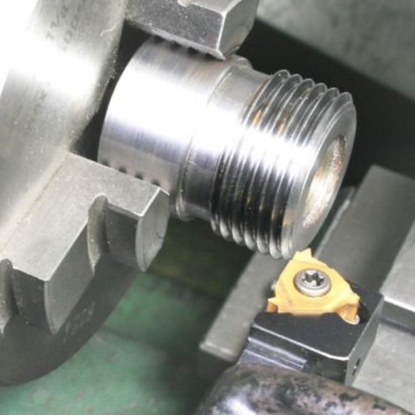
Threading on a Lathe
You can use a single-point tool for external threads cuts. The tool's path and depth of cut are controlled for correct pitch diameter, starting from a blank at the major diameter.
Tapping Thread
A tap is used to cut internal threads into a pre-drilled hole. The tap is rotated and cutting edges form the threads to get desired depth and pitch diameter.
Conclusion
Pitch diameter circle is an imaginary cylinder from the middle of a screw's threads. It has equal width of the thread and the width of the space between threads. It is used for proper fit and load-bearing capacity between interna and external threaded parts. Gauging is done with tools three-wire method in diameter measuring, to verify the pitch diameter meets design specifications. The design specifications are essential to prevent assembly problems and component failure.
FAQs
What is M6×1-6H in drawings mean?
M shows the thread in metric, 6 is the major diameter 6mm, 1 is pitch, 1mm and 6H is the tolerance specification for an internal thread.
Is pitch diameter a real measurable diameter?
Yes, it is measurable but it's imaginary and needs tools like a thread micrometer or the three-wire method to measure indirectly.
How does pitch relate to pitch diameter?
Pitch measuring is the axial distance between a point on a screw thread and the corresponding point on the next thread. And pitch diameter circle is imaginary intersecting the threads where the thread's width equals the groove's width.
How do I measure internal thread pitch diameter?
It is measured by "three-wire method" with a high-precision micrometer and wires.
 NDA Agreement in Machining: A Complete Guide