Tel/WeChat:
  Email:
 Home
HomeMechanical Joint vs. Flange: Choosing the Right Connection for Your Project

 Published:Jun 16,2025
You see huge systems of oil & gas pipes. These pipes must be securely connected to prevent any leakage. Any leakage causes a loss of money and, in the case of gases, can lead to explosions. This article introduces you to the most important members of the pipe industry. We are going to discuss two main things, which are mechanical joints and flanges. The choice between these two components depends on pressure, design, cost and many other things. So, let's start with a little introduction to mechanical joints and flanges.
What Are Mechanical Joint and Flange Connections?
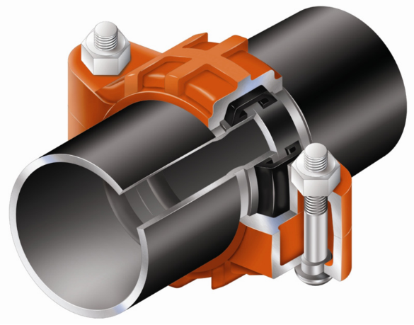
If you need quick, low-pressure setups like water mains, mechanical joints do the job. They use rubber gaskets and T-bolts to provide strong joints. They prevent failures by letting you tolerate misalignment.
Meanwhile, flanges are used when you have extreme conditions such as high pressure. They do the job when you need precise and strong, faultless joints.
Design and Core Parts
Both components have different designs to provide different properties. If you have mechanical joints, the core parts include a bell, gland, gasket and T-bolts for compression sealing. They are used when you need quick assemblies.
Flanges have different core parts such as a hub, face, gasket and stud bolts. These core parts make sure the high-pressure sealing only if you do it precisely.
Mechanical-Joint Components
Let us briefly discuss these core components:
- Bell:The part you slide over the pipe end (fits 3-64" pipes)
- Gasket:The rubber ring you compress (15-20%) to create the seal
- T-bolts:The bolts you tighten (35-50 ft-lbs) to squeeze everything together
- Gland:The metal piece you use to evenly press the gasket
- Why You Choose MJs:
- ✓No welding: perfect when you need emergency repairs
✓ Fast installation: that's why Philadelphia uses them for 90% of its water lines
Flange Components
- Hub:The part you weld or thread onto your pipe (common materials like ASTM A105 carbon steel)
- Face Types-Choose Based on Your Needs:
- RF (Raised Face):The serrated surface (1/16" height) you use for general service
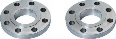
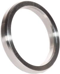
- RTJ (Ring-Type Joint):The grooved face you need for ultra-high pressure (10,000+ psi, like API 6A wellheads)
- Stud Bolts:ASTM A193 B7 grade, which you torque to 75% yield strength for secure sealing.
- Example Application:ExxonMobil's refinery uses RTJ flanges where you need to handle extreme conditions (e.g., 1,200°F crude oil lines).
Common Materials and Sizes
These are the common materials and sizes which are often used for mechanical joints and flanges.
|
Type |
Material |
Size Range |
Why It Works |
|
Mechanical Joint |
Ductile iron (ASTM A536) |
3-64" |
Flexible, corrosion-resistant |
|
Flange |
Stainless steel (A182 F316) |
1/2-24" |
Handles acids, 1,000°F+ temps |
Sealing and Alignment: Mechanical Joint vs. Flange
In this section, we will differentiate between MJs and flanges based on sealing and alignment. Oil & gas pipelines, which are buried, often use mechanical joints. They are used for flexible compression gaskets that tolerate misalignment. As mentioned earlier, flanges are used for extreme conditions.
How a Compression Seal Works
When you use MJs, many core parts do the job, for instance, the EPDM gasket compresses radially, sealing watertight while forgiving ±5° misalignment. If pressure exceeds 1,000 psi, you can't use MJs because they cause pressure surge failures.
How a Face Gasket Works
For leak-proof flanges, it is important that you maintain a 30,000-psi bolt preload (graphite gaskets) and ≤3.2 µm flatness. Always re-torque bolts after 24 hours to prevent gasket creep. A Texas oil rig leaked when uneven torque compromised Class 900 flanges, showing why precision matters.
Axial Thrust and Misalignment Risks
If there is ±5° misalignment, mechanical joints will fail at over 1,000 psi without restraints. So, how will we tackle this failure? Simple, you can use flanges, they can resist pressure over 1,000 psi easily, but with perfect alignment. You can use MJs for buried pipes.
Pressure-Temperature Ratings: Mechanical Joint vs. Flange
During the applications, the possibility of high temperature or pressure always remains. That is why you must know the limits of using MJs and flanges. Let's see their capabilities for both maximum temperature and pressure.
Mechanical Joint Limits
There is a standard "AWWA C111" which guides about the capabilities of MJ for both T and P. For instance, at a temperature of 75°F, its maximum pressure capacity is 350 psi. But as T rises let's say "400°F", the pressure capacity drops to 150 psi only.
Flange Limits
For flange, use ASME B16.5 for guidance about flange limits. At 100°F T, flanges can bear pressure up to 6,400 psi. As T rises, P capacity decreases.
How to Choose Materials for Your Connection System?
The following table shows what material is best for which application:
|
Material |
Standard |
Key Properties |
Limitations |
Best Use Cases |
|
Carbon Steel |
A105 |
Budget-friendly, suitable for most jobs |
Brittleness and cracking in sour gas or freezing temperatures |
General applications |
|
Duplex Steel |
A182 F51 |
Resists chlorides, maintains 1,440 psi strength at 500°F |
Higher cost |
Offshore, chemical handling |
Machining Workflows for Mechanical-Joint Hardware
To work with MJs, you have the freedom of fast production due to simpler production. Their forgiving design makes MJs ideal for high-volume water projects-just ensure your bell, gasket, and gland meet AWWA standards for reliable performance.
1. Blank Preparation
The first step of the machining workflow is blank preparation. For blank preparation, the material is heated at 1,100°F for 1 hour to prevent warping before machining. It ensures that the dimensions of the components do not alter till the final step. ASTM A536 standard is followed for this step.
2. Turning & Drilling
Turning & Drilling procedures in CNC lathes make sure the precision of parts. The blanked MJs parts are shaped using turning and drilling operations. For bells and glands, 500 SFM cutting speeds with a 0.012 in/rev feed rate are used. While the bolts slots are drilled using HSS tools running at 1,200 RPM with a 0.008 in/rev feed for clean, accurate holes.
3. Surface Finish:
For surface finish, use a profilometer. It is necessary to obtain a gasket seat with a smooth surface finish to achieve Ra ≤ 3.2 µm.
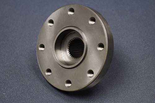
Machining Workflow for Flange Hardware
Why tolerances thinner than a human hair (<0.003") and mirror-like finishes (Ra ≤1.6µm) make all the difference:
✔ Leak-Proof Guarantee Meets strict ASME/API standards for critical applications
✔ Failure-Proof Performance Essential for oil/gas systems where leaks are catastrophic
✔ Battle-Tested Reliability Withstands 15,000+ psi pressures and 1,200°F temperatures
1. Roughing & Profiling
Start with ring-rolled forged blanks, 0.1" oversized for machining. Your CNC lathes first contour the hub and backface, creating critical reference surfaces. For flanges 24"+, verify material integrity with ultrasonic testing before final machining - this ensures leak-proof performance in high-pressure applications.
2. Facing & Finishing
For flawless sealing surfaces, machine RF faces to Ra 1.6µm or cut RTJ grooves within ±0.001" tolerance. Use PVD-coated carbide tools with 0.004 in/rev finishing passes to achieve leak-proof performance in critical applications. This precision ensures ASME/API compliance for high-pressure systems.
3. Drilling & Tapping
Drill bolt holes within ±0.001", then thread mill for uniform preload. Spot-face each hole to ensure proper nut seating and gasket performance.
4. Inspection & Verification
To ensure flawless performance, you conduct three critical inspections:
- Precision Alignment Verification
- Confirm flatness (<0.003"/in) and bolt hole positioning using CMM technology
- Surface Perfection Analysis
- Measure micro-scale roughness (Ra values) with handheld profilometers
- Structural Integrity Testing
- Perform dye-penetrant examinations on mission-critical components to reveal subsurface defects
CNC Precision Machining Flange
Modern 5-axis CNC machining enables the completion of flanges in a single setup, thereby eliminating fixturing errors. This ensures dimensional perfection for critical nuclear and subsea applications where precision is non-negotiable.
Cost and Lead-Time Analysis
Your decisions impact cost and speed. Compare forging and billet options, and find the right balance between fast machining and tool durability. This helps you get the best results for flanges and mechanical joints at the lowest cost.
Blank Forging vs. Billet Machining
Choose your blank type wisely, costs and applications differ sharply:
|
Factor |
Forging |
Billet Machining |
|
Cost |
$8-$15/lb |
40% material waste |
|
Setup |
$5k-$20k dies cost |
No die costs |
|
Best For |
High-volume (>500 units) |
Prototypes/custom jobs |
Cycle Time vs. Tool Wear
You can machine parts 25% faster by cutting them more aggressively. The best approach is:
- Use carbide tools at medium speed (0.006 in/rev feed, 600 SFM)
- Get 2 hours of tool life instead of just 40 minutes
- Like one refinery that saved $18,000 every month this way
When to Choose MJ vs. Flange
If the application is underground or low-pressure, then prefer MJs. But in the case of high pressure, use flanges. In simple words, it all depends on pressure rating, installation environment and future excess needs.
When Mechanical Joints Win
When pressure is low, such as <350 psi, MJs win because they are cost-effective.
When Flanges Win
For high pressure, i.e. 15,000 psi, use flanges. Because their bolted design maintains the system's safety even under high pressures at high temperatures.
Conclusion
We conclude that if the pressure is between 150 psi to 350 psi, you should go for MJs because of a 40% cost-saving on installation. But for extreme conditions, such as 6,400 psi pressure and 1500oF temperature, flanges are the perfect choice. For corrosion protection, you can use polymer coatings on flanges or MJs. A wise selection between MJs and flanges can reduce failures up to 72%. Do not forget to follow ASME B16.5 and AWWA C111 standards while working with MJs and flanges.
From this article, you can easily understand that the tolerance and surface quality of mechanical joints and flanges are very essential for their connection functions in industrial applications. As an experienced CNC machining manufacturer, Tuofa manufactures mechanical joints and flanges with precision dimensions and high-quality surface.
FAQs
Do I need a flange every 6 meters?
Only if your pipe material (like PVC) requires extra support. The steel pipes often let you span 12+ meters without them.
Flange vs. coupling?
Use couplings for permanent joints, but choose flanges when you need disassembly, like for valve replacements or maintenance access.
What causes sealing failure in mechanical joints and flanges?
Uneven bolt torque and gasket creep are common factors for sealing failure in mechanical joints and flanges. Because the misalignment between two connected parts can accelerates wear. Keep proper installation ensures the performance of mechanical joints and flanges.
 Car Chassis Guide: Types, Functions & Custom Solutions