Tel/WeChat:
  Email:
 Home
HomeHow to Machine Thin Walled Parts? -An A-Z Guide

 Published:Nov 17,2025
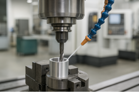
In certain designs, the wall thickness for parts is kept at a minimum due to some factors like lowering weight, accommodating constricted spaces, or even heat dissipation. As an example in aerospace industry, the lighter the aircraft the better fuel efficiency it gives. But machining thin-walled parts is a challenging task. Only efficient machining strategies deliver good results. Let’s look into how to machine thin-walled parts.
What Are The TOP 6 Most Difficult Machining Situations?
Machining is a very versatile shaping technique. While it enables manufacturing with a high precision, it is not always easy to perform. Complex shapes require a high level of operator’s skills, robust CAM programming and an advanced machining setup. The below Youtube video shows the machining of a very difficult part. Carefully look how smoothly it is being made by a CNC machine:
Here are top 6 difficult machining situations:
1.Thin Walls Parts
The biggest challenge in thin wall milling and machining is distortion and vibration due to a thin wall thickness. Tool deflection, heat buildup, and cutting forces can damage the workpiece. An efficient machining strategy can successfully produce thin walled parts.
2.Deep Narrow Pockets
Maintaining a good precision in deep narrow pockets is a big challenge. Chip evacuation and heat build up remains a hurdle. Specialized tools, high-speed machining and optimized coolant flow can help in producing such features.
3.Long-Reach Internal Cavities
Long-reach internal cavities require extended tools. But these tools are prone to vibration and deflection. Use of efficient toolpath planning, step-down passes, and damping tool holders are effective in this situation.
4.Deep Internal Threads
Chip accumulation is the biggest detriment in producing deep internal threads. These accumulated chips speedup wearing out of tool. Tools with more flutes and other chip evacuation mechanisms facilitates in production.
5.Hard-to-Machine Alloys
Hard to machine alloys like titanium and Inconel have high strength and low conductivity. Specialized carbide or ceramic tooling and precise feeds and speeds are thus required.
6.Multi-Axis CNC Machining
Although multi axis CNC machines can produce very intricate shapes but there are some limitations. Advanced CAM programming, precise calibration, and skilled operators are a must for multi axis CNC machining. TUOFA provides 5-axis machining with a high level of customer satisfaction. We have a well-trained team of engineers who have the ability to do a fool proof CAM programming. Our skilled operators setup up the workpieces and tools with a high precision.
What Counts as a Thin Wall?
In CNC machining, thin-walled parts are those sections in which deflection can be caused by cutting forces. Usually, parts thinner than 2mm or those having a height to thickness ratio of 10:1 or more are counted as thin-walled parts. These components require special machining procedure for their manufacturing.
Definitions by Material and H:t / L:t Ratios
The H:t and L:t criteria vary from material to material. The table presents a general guide for some common materials:
|
Material |
H:t Ratio |
L:t Ratio |
Notes |
|
Aluminum |
8–15:1 |
up to 30:1 |
Easy to cut but prone to vibration and heat distortion. |
|
Steel |
6–10:1 |
up to 20:1 |
Needs rigid support and careful toolpaths. |
|
Titanium / Inconel |
4–8:1 |
up to 15:1 |
Strong but hard to cut; high cutting forces. |
Typical Failure Risks
Deflection
Deflection causes the walls to bend or distort under cutting load. It can cause dimensional inaccuracy and poor fitting of components.
Chatter
Chatter ruins the surface finish. It occurs because of tool vibrations. As walls become thin, they become flexible. The cutting load on tool causes it to vibrate against non-rigid walls.
Heat Growth
A thin wall thickness for CNC machined parts is not sufficient to resist warpage due to thermal loads. Even a small heat accumulation can result in failure.
Key Factors Affecting Thin Wall Machining
Understanding the factors that affect thin wall machining on lathes is the key to produce flawless parts consistently. CNC machinists must be aware of how to machine thin walled parts properly. Knowledge of the factors that affect operational efficiency and product quality helps to devise a good machining strategy.
Material and Wall Geometry
The minimum machinable wall thickness varies with the type of materials. The H:t and H:L ratios also have an impact on the minimum wall thickness. So, incorporation of the correct wall thickness is necessary to produce CNC parts flawlessly.
Workholding Stiffness and Support Span
A rigid workholding setup prevents vibration, tool deflection and chatter. Quite often thin wall machining requires custom fixtures and supports.
Tool Rigidity and Reach
Long tools tend to vibrate more. So, shorter and rigid tools are desired for thin wall machining.
1.Design for Machinability Before You Cut
Thin walled parts on lathes require a perfect design. The design must incorporate features that are consistent with the machine’s capabilities. Even small features like fillets and ribs can add great rigidity to thin walled parts. Let’s learn about how to machine thin walled parts with design efficiency.
Set Minimum Walls and Floors
Wall thickness for CNC machined parts needs to be within the minimum specified range. The minimum wall thickness varies from material to material. Tolerance for surface treatments like anodizing must be considered. Anodizing adds thickness to the walls. The below tables give design guidelines pertaining to wall thickness for common materials.
Metals Guidelines
|
Material |
Min. Wall thickness (mm) |
H:t Ratio |
Comments |
|
Aluminum 6061 |
1.0-1.5 |
8-15:1 |
Good rigidity and machinability. |
|
Stainless Steel 304 |
1.5-2.0 |
6-10:1 |
May warp if unsupported. |
|
Titanium Grade 5 |
1.0-1.2 |
4-8:1 |
Requires sharp tools and low feed. |
|
Inconel 718 |
1.5-2.5 |
4-6:1 |
High cutting forces and heat buildup. |
Plastics Guidelines
|
Material |
Min. Wall Thickness (mm) |
Comments |
|
ABS |
1.0-1.5 |
Avoid long unsupported spans. |
|
POM (Delrin) |
1.0-1.2 |
Stable and easy to machine. |
|
Nylon |
1.5-2.0 |
Watch for heat deformation. |
|
Acrylic |
2.0-3.0 |
Brittle; use low feed and sharp tools. |
Add Some Stiffness
Ribs
Addition of even small ribs can add a high level of stiffness to the CNC parts. The risk of warpage, distortion or bending reduces quite significantly.
Bosses
Bosses are added around thin walled holes to prevent dimensional inaccuracies. As the holes become stiffer, they facilitate in proper fitting during assembly.
Fillets
Sharp corners are very difficult to machine. They damage the tool and produce chatter during machining. On the other hand, if fillets are added, machining becomes easier and stress distributes over the fillet area instead of concentrating around sharp corners.
Plan Tool Access and Corner Radii
As already discussed, sharp corners are difficult to machine. If the tool radius matches the fillet radius, machining becomes easier. So, the corner radius should desirably be more than tool tip radius.
2.Choose Right Cutting Tools
Cutting tool is one of the most important components of the machining process. So, the selection of the correct tools is necessary. As a rule of thumb, the cutting tool must be sharp and hard for thin wall machining. The machining parameter should be such that low force and high RPM are applied.
Low-Force Tooling
Cutting tools that designed for low force are effective in thin wall machining. Such tools have polished flutes, sharp edges, smaller tip radii, and high rake angles.
Tool Material and Coatings
Compatibility and cost of tool materials is a considerable factor in thin wall machining. Generally, the sharper and harder the tool the better the machining efficiency. But the cost of tool material at time makes machining unfeasible. Here is a general guideline of how to machine thin walled parts with the right tooling material:
|
Tool Material |
Suitable For |
|
Carbide |
Aluminum, steel |
|
Cermet / Ceramic |
Inconel, Titanium |
|
HSS |
Soft metals, plastics |
|
CBN (Cubic Boron Nitride) |
Hardened steels |
|
PCD (Polycrystalline Diamond) |
Aluminum, composites |
|
Coated Carbide |
Stainless steel, tool steel |
3.Machining Strategies for Thin Walls
Thin wall machining requires specialized machining strategies. In contrast to traditional machining, CNC machining of thin walled parts need minimum deflection, minimum wear and low cutting forces. Here we will be discussing some common machining strategies for producing thin walled parts.
For Milling Operations
Machining Sequence
As a rule of thumb, start machining thicker sections first and then move onto thinner sections. This sequence helps to maintain stiffness at the time of machining thin sections.
1.Climb Milling
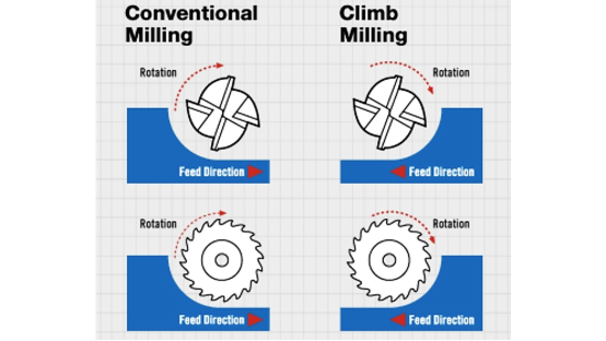
In contrast to traditional milling, in climb milling the direction of rotation of the tool and the feed is the same. In this way, tool penetrates at maximum cutting depth but ultimately remove thin chips. Cutting forces lowers and shearing action become smoother. As a result, there is less deflection and vibration during machining. Climb milling can be used in 3-axis and 4-axis machining processes.
2.Trochoidal Milling
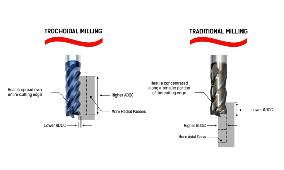
In trochoidal milling, circular overlapping paths are used for cutting. In this way, the contacting part of tool is reduced. As a result, friction and heat build up reduces. As cutting forces are reduced, deflection and vibration also reduce.
3.High-Speed Machining (HSM)
In HSM, the feeds and speeds are fast but the cutting force is low. It results in less deflection, less friction and less wearing out of tools.
For Turning Operations
1.Simultaneous Roughing and Finishing
If rouging and finishing passes are given simultaneously, there is less pressure build up and distortion.
2.Constant Surface Speed (CSS)
A steady surface speed results in consistent chip formation. It will be a pulling action by the tool instead of a tearing action.
Control Heat and Vibration
Heat buildup and excessive vibrations are big detriments to the quality thin walled CNC parts. Options should be carefully chosen to prevent heat buildup and vibrations. Here we will be discussing how to machine thin walled parts in this scenario.
Coolant Choices
Coolant choices vary from situation to situation. For example, in thin wall milling of aluminum or steel, flood coolant is used. But in case of Titanium or Inconel, pressure coolant is used. Another example is of High Speed Milling (HSM), excessive coolant can cause splatter. So, minimum quantity lubrication (MQL) or air-oil mist is used.
Damping Aids
Vibrating is a big detriment to surface finish and dimensional accuracy in thin wall milling, Use of visco pads and filled fixtures can damp out vibrations.
Chip Evacuation
Chip accumulation in thin wall milling can unintentionally wear out areas. It also causes heat buildup. Chip evacuation mechanism should be robust. A combination of good flutes geometry and air blast helps to evacuate chips. If trochoidal milling is opted instead od traditional milling, chips evacuate naturally.
5.Turning and Mill-Turn Thin Sections.
Boring Thin Sleeves and Tubes
Boring thin wall stainless steel tubing requires careful control. The part is prone to flexing. To keep pressure low, it’s best to use sharp tools with a positive rakes. The work should be supported firmly. Several light cuts are better than a few heavy cuts.
Grooving and Parting
Grooving and parting of thin walled parts is a highly critical step. For successful machining in this scenario, use narrow, sharp tools with positive rake geometries. Constant surface speed (CSS) is a good strategy. It maintains chip consistency. Coolant flow should also be optimum depending on conditions.
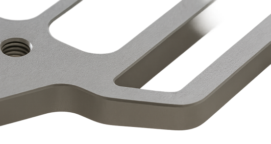
Practical Case: UAV 7075-T6 Avionics Chassis
Lets look into a practical case of machining high precision thin walled part. Its an UAV 7075-T6 Avionics Chassis. Aerospace parts require a high level of precision. Even a slight deviation from the design makes the part rejected. Let’s check out the machining solution for such demanding products.
Product Specifications
UAV avionics chassis is made up of 7075-T6 aluminum plate. The dimensions of the chassis are 220 × 160 × 28 mm. The wall thickness is just 1.2mm. Production volumes range from batch production of just 50 – 100 pcs to mass production of around 20000 pcs.
Machining Requirement
Machinating requirements of avionics chassis are stringent. The tolerances are tight. Maintaining flatness with a CNC machining wall thickness of just 1.2mm is challenging. The holes should be perfect to ensure proper fitting. Design features like ribs and fillets are also challenging with the small wall thickness. If cutting force becomes too high or if tool holding setup is not rigid it can easily ruin the workpiece.
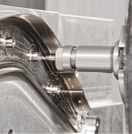
Thin Wall Part Machining Solution
The main key to produce high quality thin walled parts is in adopting an efficient machining strategy. The conditions of machining should be thoroughly studied. Some of the machining solution for producing thin walled parts are listed below:
- Climb milling
- Trochoidal milling
- HSM
- HEM
- Specialized tools
- Specialized workholding
- Specialized tool holding
- Incorporation of stiffness enhancers in design
TUOFA provides specialized solution of CNC machining for thin walled parts. Our dedicated engineering team optimizes machining process according to the conditions. We have state of the art CNC machining facility equipped with advanced tools to produce high quality thin walled parts.
Conclusion
Machining of thin walled parts is a challenging task. It requires specialized machining strategies, specialized tools, specialized controls and a good design. Preventing deflection and vibration is highly critical. A slightest mistake in thin wall milling can make the part useless. Maintaining dimensional accuracy and precision is highly important to ensure proper fit.
FAQs for Thin-Walled Machining
What height-to-thickness ratio is realistic for aluminum?
8-15:1 is considered a realistic H:t ratio for aluminum. H:t varies from one grade of Aluminium to another.
How thin can walls be on stainless before chatter dominates?
Thicknesses above 2mm should be safe.
Is vacuum fixturing safe for small parts?
It depends on the surface area on which vacuum is applied. Larger surface area produces more suction.
What toolpath works best for tall, flexible fins?
Climb milling should be a good option. It minimizes deflection and chatter.
 Side Milling: All About Milling Process and Materials Choices