Tel/WeChat:
  Email:


 Home
HomeQuality Testing for CNC Machined Parts

 Published:Jul 15,2026
Computer Numerical Controlled machines are used basically when the part's machining should be flawless. In critical industries, such as aerospace, automotive, energy sector, and medical industry, these machines are very important for the manufacturing of different parts. Although these machines produce parts with efficiency and accuracy, they still do not guarantee that these parts are produced to tight tolerances.
To confirm whether it meets all the specifications and tolerances, quality testing is an important step that is performed from the first step, i.e., material procurement, to the final product before being employed in the application. This article provides insights into how quality testing plays its role in CNC machined parts.
Why Is Quality Testing CNC Parts Important?
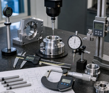
Quality testing basically refers to checking dimensions, geometric accuracy, surface finish, material properties, and functional characteristics by using different quality testing tools, such as a micrometer, a screw gauge, a Coordinate Measuring Machine (CMM), laser scanners, surface roughness testers, etc.
Quality testing is important for CNC machined parts because any error in dimensions, surface finish, etc., is capable of affecting the part's performance, durability, and reliability.
Quality Assurance vs Quality Control vs Quality Testing
Quality assurance, quality control, and quality testing are interlinked terms, but there are some differences, which are given in the following table:
|
Aspect |
Quality Assurance (QA) |
Quality Control (QC) |
Quality Testing (QT) |
|---|---|---|---|
|
Focus |
Prevent defects |
Detect defects |
Verify performance and functionality |
|
Approach |
Process-oriented |
Product-oriented |
Test-oriented |
|
When |
Before and during production |
During and after production |
During or after production |
|
Goal |
Build quality into the process |
Ensure product meets specifications |
Confirm the product works as intended |
|
Activities |
Process planning, SOPs, audits, training |
Inspection, measurement, sampling |
Functional, performance, and reliability tests |
|
Example |
Creating inspection procedures |
Measuring part dimensions |
Testing whether a product operates correctly |
What Should be Inspected on a CNC Machined Part?
CNC machines machine the parts with high accuracy, no doubt, but there is no confirmation whether the part is produced strictly according to the geometric or functional requirements. So, quality testing should be used to inspect different features of CNC machined parts. These features include:
- Dimensions(length, height, thickness, radius, groove, etc.)
- Surface Finish(surface roughness, scratches, sharp edges, burs, etc.)
- Geometric Accuracy(flatness, cylindricity, concentricity, position, runout, etc.)
- Assembly Critical Features(alignment of holes, clearance and interference fits, etc.)
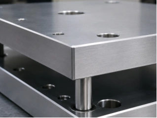
- Features Inspection(hole depth, splines, keyways, tapers, etc.)
Test Part Dimensions and Tolerances
Quality testing is performed to ensure that the dimensions of the part are according to the drawing and allowable dimensional variations specified on the engineering drawing. This step is important to perform because if there is any flaw, for instance, a length difference of only 0.5mm for an aircraft part, it can lead to the failure of that part during the operation.
Which Part Dimensions Need to be Measured?
In a CNC machined part, the following dimensions are required to be measured, and ensure that they are correct or not:
- In overall dimensions
Overall length
Overall width
Overall height
Thickness
- In diameters
Outside diameters
Inside diameters
Counterbore diameter
Countersink diameter
- Hole dimensions
Hole diameter
Hole depth
Hole location
Center-to-center distance between holes
- Thread dimensions
Major diameter
Minor diameter
Pitch diameter
Thread pitch
Thread depth
- Chamfers
Chamfer width
Chamfer angle
Which Tools Are Used for Dimensional Inspection?
Tools to be used for quality testing of CNC machined parts are chosen based on the type of dimension to be inspected. This section briefly discusses the different kinds of tools for different kinds of dimensions:
- For linear dimensions (length, width, thickness), a steel rule, a vernier caliper, a digital caliper, and a micrometer are used.
- For high-precision inspection of the outside diameter, a laser micrometer is used.
- For inside diameter inspection, a bore gauge can be used. Vernier caliper can also be used, but it is not precise.
- For the inspection of groove width and depth, an optical comparator and CMM are used.
- To inspect thickness with high precision, an ultrasonic thickness gauge can be used.
Verify Geometric Accuracy in CNC Parts
Verification of geometric accuracy in CNC machined parts means checking that the shape, orientation, and spatial relationship of the machined features meet the specified GD&T requirements on the engineering drawing. It means it is not just about the sizes being correct. It verifies whether the feature is in the correct size and in the correct position.
Which Geometric Features Need to be Checked?
The following geometric features are important with respect to the part's applications and so should be inspected:
- Straightness
- Cylindricity
- Parallelism
- Perpendicularity
- Angularity
- Position
- Concentricity
- Runout
Which Tools Are Used to Verify Geometric Accuracy?
- A Surface plate and a dial indicator are used to verify the flatness of the CNC-machined part. For higher precision, an optical flat tool is used.
- For straightness, straight edge and CMM are used.
- To check cylindricity, a roundness measuring machine and a CMM are used
- Height gauge and dial indicator for parallelism
- Precision square and CMM are used to verify the perpendicularity of the part
- For angularity, a bevel protector and a sine bar with gauge blocks are used
Inspect Critical Features on CNC Parts
The following are the critical features of CNC-machined parts that should be inspected using different relevant tools.
Test Threaded Features
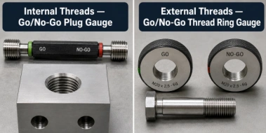
There are many types of threads in a CNC-machined part that serve different purposes. For instance:
- Internal threads are made for bolts, screws, etc.
- External threads serve to fasten nuts, pipes, and connector assemblies, etc.
Different tools, such as Go/No-Go plug gauge is used for internal threads, and Go/No-Go thread ring gauge is used for external threads. Inspection of these threads makes sure that they remain within the specified allowable variations according to the drawing.
Test Hole Features
Through holes, blind holes, reamed holes, counterbored holes, and countersunk holes are the most important hole features in a CNC-machined part. For instance, a counterbored hole is used as a recess for socket head cap screws. To inspect these holes, multiple tools are used:
- Plug gauge
- CMM
- Vernier Caliper
- Bore Gauge
- Countersink Gauge
- Optical Comparator
Test Groove and Slot Features
Different types of grooves and slots are made in a CNC-machined part, for instance, straight slot, keyway slot, T-slot, circular grooves, snap ring grooves, relief grooves, etc. During their inspection, their width, depth, parallelism, perpendicularity, and locations, etc., are inspected using different tools such as:
- Vernier caliper, CMM, micrometer, etc., for slots
- Depth gauge, radius gauge, optical comparator, etc., for grooves
Test Sealing Features
Sealings in CNC-machined parts are made to control leakages of fuels, gases, vacuum, or pressure, etc. So, their inspection is very important to prevent any kind of loss. Different types of sealings include O-ring groove, dynamic O-ring groove, gasket sealing face, flange sealing surface, etc. To inspect these sealings, the following tools are used:
- Surface Plate
- Dial Indicator
- Flatness gauge
- Sine Bar
- CMM
Inspect Surface Quality on CNC Parts
Surface quality is an important part of CNC-machined parts because they affect fatigue life, so its inspection is important to discuss.
How Is Surface Roughness Measured?
Surface roughness refers to how the surface is, such as whether it is smooth or rough. To inspect surface roughness, different tools are available, such as:
- Contact Stylus Profilometer
- Optical Profilometer
- Atomic Force Microscopy
- Interferometry
To measure the surface, the microscopic left on the CNC-machined parts is measured through the above-mentioned tools. It is measured in Ra, Rz, Rt, or Rq values.
How to Inspect Edge Conditions?
Edge conditions mean the state of the edges of a CNC-machined part. These edges include sharp edges, burrs, chamfers, radii, break edges, rolled edges, and feather edges, etc.
- Visual inspection
- Chamfer inspection through a vernier caliper or CMM
- Radius inspection through radius gauges, optical comparator, etc.
- Burr height measurement using a digital microscope
The above-mentioned tools are used to inspect the edges of the CNC-machined parts.
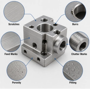
Surface Defects
Surface defects include scratches, burrs, feed marks, chatter marks, porosity, and pitting, etc. Different tools can be used to identify these defects. These tools include:
- Digital microscope for burrs
- Surface roughness tester for feed marks
- Profilometer for chatter marks
- Dye penetrant or magnetic particle inspection for surface and subsurface cracks
Inspect Surface Finishes After CNC Machining
This section provides insights into how surface finishes of CNC-machined parts are inspected.
Coating Thickness and Coverage
CNC-machined parts are sometimes coated to prevent corrosion or thermal effects at high temperatures. Coatings are inspected to check whether they are thick or cover all the parts uniformly or not. To inspect coating thickness and coverage, coating thickness gauges, microscopic cross-section measurements (SEM), X-ray fluorescence, UV inspection, etc., are used.
Coating Adhesion
Coating adhesion is inspected through a pull-off adhesion tester, cross-hatch adhesion tester, scratch adhesion tester, Rockwell indentation adhesion test, and bend test equipment.
Dimensional Changes on Critical Features
Critical dimensions may change after undergoing any coating process. To inspect those dimensions, vernier calipers, outside micrometers, bore gauges, thread gauges, CMM, and optical comparator can be used.
Test Functional Performance of CNC Parts?
After CNC machining, the parts undergo different kinds of functional tests to examine their behavior under the actual application conditions.
Pressure Resistance Testing
This testing is performed to examine whether the part contains fluids or gases safely under certain pressure. The examples of such parts are valve bodies, rocket engine components, heat exchangers, etc. During this testing, the part is filled with water or gas and pressurized to a specific pressure. The pressure is defined for a certain time period to check for any kind of leakage, deformation, or crack.
Leak Testing
It is a non-destructive testing, performed to inspect whether the part is capable of containing fluid or gas without any leakage. Bubble leak test, water immersion, pressure decay test, and vacuum decay test are performed in leak testing.
Torque Testing
If the aim is to check whether the CNC machined part is capable of bearing twisted load without failure or deformation, this test is performed.
- Thread torque test
- Torque-to-failure test
- Torque ranches
- Digital torque analyzer
The above-mentioned tests and tools are used in torque testing.
Practice: Common CNC Part Quality Problems and Their Causes
In quality control of CNC-machined parts, these are the problems that appear:
Correct Dimensions but Assembly Jamming
The following table shows the possible causes of incorrect dimensions and their impact on seal failure:
|
Cause |
Description |
Result |
|---|---|---|
|
Burrs on edges |
Material left on edges |
Assembly jamming |
|
Sharp corners |
No edge relief |
Interference during fit |
|
High surface roughness |
Excess friction |
Difficult assembly |
|
Incorrect GD&T |
Poor feature alignment |
Improper fit |
|
Hole or shaft misalignment |
Mating features offset |
Assembly failure |
Correct Hole Size but Incorrect Hole Position
The following table shows the possible causes of wrong hole position:
|
Cause |
Description |
Result |
|---|---|---|
|
Incorrect workpiece setup |
Wrong work offset |
Hole shifted |
|
Fixture misalignment |
Part not clamped correctly |
Hole misplaced |
|
CNC program error |
Incorrect coordinates |
Wrong hole location |
|
Machine positioning error |
Axis backlash or poor calibration |
Position deviation |
|
Tool deflection |
Tool bends under cutting load |
Hole |
Acceptable Surface Finish but Poor Assembly Fit
The following table shows the possible causes of poor surface finish and their impact on assembly fit:
|
Quality Problem |
Possible Cause |
Impact on Assembly |
|---|---|---|
|
Acceptable surface finish but poor assembly fit |
Incorrect geometric tolerances (GD&T) |
Mating parts do not align properly despite a good finish. |
|
Dimensional variation within tolerance stack-up |
Combined tolerances result in an improper fit. |
|
|
Part distortion after machining |
Changes the actual fit without affecting surface finish. |
|
|
Burrs or edge defects |
Obstruct smooth assembly even though the surface finish is acceptable. |
|
|
Incorrect feature position |
Functional features do not mate correctly despite an acceptable finish. |
Acceptable Roughness but Seal Failure
The following table shows the possible causes of surface roughness and its impact on seal failure:
|
Quality Problem |
Possible Cause |
Impact |
|---|---|---|
|
Acceptable roughness but seal failure |
Incorrect surface waviness |
Prevents uniform sealing contact. |
|
Improper groove dimensions |
Causes inadequate seal compression. |
|
|
Out-of-flat sealing surface |
Creates leakage paths despite acceptable roughness. |
|
|
Burrs or edge defects |
Damages or prevents proper seating of the seal. |
|
|
Incorrect geometric tolerances (flatness/runout) |
Reduces sealing effectiveness even when roughness meets specification. |
How Does Tuofa Manage CNC Parts that Do Not Meet Requirements?
It is impossible to machine a batch of parts without any issues. That is why knowing how to handle defective parts is also one of the standards for evaluating the manufacturing capability of a reliable CNC machining service provider. With many year of manufacturing experience, Tuofa carries out the following measures to prevent defective parts from delivering to our customers.
Identify and Segregate Nonconforming Parts
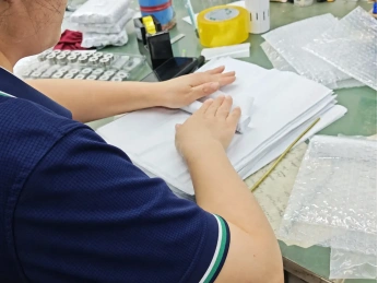
In the very first step, our highly experienced staff identifies and segregates nonconforming parts from the lot. Tuofa provides two full quality inspections before and after surface treatment. Even in the packaging step, our staff also checks the quality of parts. These CNC-machined parts are segregated based on any defect or dimensional error.
Determine Whether the Parts Can be Reworked or Repaired
In the second step of managing nonconforming parts, Tuofa's expert professionals check whether the part can be reworked or repaired. The experience of our staff helps us in managing nonconforming CNC-machined parts quickly and accurately.
For example, surface issue like burrs and mild surface contamination are possibly repaired, while oversize holes or critical feature position is out of tolerance can't be simply repaired. Importantly, the repaired parts should be tested again for their dimension, surface or functions.
Review the Cause Before Continuing Production
At Tuofa, the cause of any error is not ignored, but reviewed by our highly experienced personnel. Generally, Tuofa checks carefully the causes of the defective parts and try to take some measures to avoid the same issues in the next production. For instance, we check the following things:
- Cutting tools
- Machining programs
- Surface treatment process
- Cleaning process of parts
After confirming the causes, we will adjust the settings.
Conclusion
Quality control is the basis of successful applications of CNC-machined parts because if any flaw goes uncontrolled, it becomes a potential source of failure at later stages. There are different tools used for the inspection of different CNC-machined parts, which are used based on the requirement. For instance, if a hole has to be inspected, then a plug gauge, CMM, etc., can be used.
FAQ
What tools and technologies are commonly used for CNC inspection?
Common tools are:
- Vernier caliper
- Bore gauge
- Micrometer
- Threads gauge
- Plug gauge
- Optical comparator
Common technologies are:
- 3D scanning
- CT scanning
- CMM inspection
- In-process probing
When is a CMM required for CNC part inspection?
A coordinate measuring machine is an advanced machine that is used when the tolerances of the part are tight and the geometry is complex.
Why should CNC parts be checked again after anodizing?
Anodizing provides a coating to the CNC-machined part. After anodizing, CNC-machined parts should be checked again to check the coating thickness and determine any changes in the dimensions of the critical features of the part.
 How to Clean CNC Machined Parts: Precision Parts Cleaning Process