Tel/WeChat:
  Email:
 Home
HomeDepth of Cut in Machining: Formulas, Limits, and Optimize

 Published:May 30,2025
An understanding of the depth of cut (DOC) is critical for achieving a good machining quality while maintaining productivity. An expert machinist should have a clear understanding of the formulas, limits and optimization of the depth of cut. In this way, an optimum material removal rate (MRR) can be achieved while considering CNC machine's capabilities.
Depth of Cut—What It Really Means
Depth of cut is an important parameter in machining jobs. Optimum DOC paves way for an optimum material removal rate (MRR) without compromising the surface finish quality. A correct depth of cut hampers any undesirable effects on tool life, workpiece material and the overall machining efficiency.
Axial DOC vs. Radial DOC
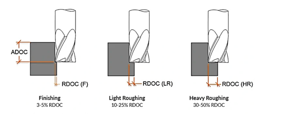
Axial Depth of Cut (ADOC) is the vertical distance that the tool penetrates into the workpiece material. On the other hand, Radial Depth of Cut (RDOC) is the width of the tool that engages with the materials. Both ADOC and RDOC affect material removal rate (MRR).
How DOC Differs From Chip Thickness And Stepover
Chip thickness just gives an average of the material thickness that is being removed per pass. While stepover gives the width of the chip that is being removed, if the chip is assumed to be flat without any curliness.
Why DOC is one-third of the machining “speed-feed-depth” triad
DOC carries 1/3rd importance in machining parameters setting. The other 2/3rd importance goes to speeds and feeds. As an example, if a machinist wants to increase the speed by 100 RPM, it will not increase MRR unless feed and depth are adjusted proportionally. A correct balance between these three will yield desirable results.
Cutting Speed, Feed Rate and Depth of Cut in CNC machining
An optimum setting of CNC cutting parameters where cutting speed, feed rate and depth of cut are balanced would give good results. An unbalanced setting can create difficulties like excessive tool wear, damage to the workpiece, poor surface finish, chatter or even inconsistent dimensions.
Cutting Speed vs. Depth of Cut
Cutting speed, usually measured in SFM, is the refers to the speed at which the cutting edge moves relative to the material. DOC is the depth at which the tool penetrates the substrate. If a cutting speed is to be increased the depth of cut should be decreased in a balanced manner, Otherwise, there could be excessive force on the tool can wear it out or even break it. It could also cause chatter and poor finish quality.
Feed Rate vs. Depth of Cut
- What is the difference between feed and depth of cut?
Feed rate is the distance the tool advances per revolution. Both of these cutting parameters should be balanced. When DOC is to be increased feed rate should be moderate to avoid overloading the tool.
Speed, Feed, and DOC—Finding the Sweet Spot
The sweetest spot lies in the right balance between speed, feed, and DOC. This should be at the point where material removal rate is sufficient, tool wear is low and surface quality is the best.
Axial vs. Radial DOC by Operation
Axial Depth of Cut (ADOC) and Radial Depth of Cut (RDOC) play different roles in different CNC operations like turning, milling and drilling. While the main objective remains to the higher productivity, a balanced setting of ADOC and RDOC is necessary. The user must the knowledgeable about these adjustments in CNC machining.
Turning (roughing groove vs. finishing pass)
In turning operations, RDOC is very small. The value of ADOC depends on factors like tool geometry, material properties, and CNC machine capabilities. In roughing passes ADOC is usually higher because MRR is prioritized over surface finish. Converse is true for finishing passes.
Milling (slotting, side-milling, HEM adaptive)
In milling tasks like slotting, the ADOC is shallower while the full width of the tool is engaged with the workpiece, i.e, RDOC is set to maximum. In side milling, both ADOC and RDOC are moderate. Partial width of the tools gets engaged. In HEM (high efficiency milling, the ADOC is kept high while RDOC is set to minimum.
Drilling & boring (step-drill vs. peck cycles)
In drilling and boring applications, radial depth of cut does not matter. The complete tool penetrates the workpiece.
Depth of Cutting Formulas and How to Calculate It
A correct calculation of the DOC is pertinent. If DOC is calculated beforehand, it helps in devising good toolpath strategies and MRR remains predictable. There are depth of cut formula and also reference tables for machinists to calculate the depth of cut beforehand.
Turning formula: DOC = (D_out – D_in) ⁄ 2
Depth of cut formula for turning is:
DOC (for turning) =(D(outer) - D(inter))/2
Where:
- Douteris the original diameter of the workpiece
- Dinner is the diameter after a pass
- It is divided by 2 because reduction has occurred on both ends across the diameter.
As an example, if the original diameter is 12mm and the new diameter after a pass is 11mm, the depth of cut would be:
(12-11)/2= 0.5mm
Milling formula: DOC = (total depth cut – previous pass)
Depth of cut formula for milling is:
DOC = Total depth cut – Depth of previous pass
Handy end-mill depth table
|
Tool diamter (mm) |
Axial DOC range (mm) |
Max DOC (mm) |
|
3 mm |
0.3 – 0.6 mm |
1.5 mm |
|
6 mm |
0.6 – 1.2 mm |
3 mm |
|
10 mm |
1 – 2 mm |
5 mm |
|
12 mm |
1.5 – 2.5 mm |
6 mm |
|
16 mm |
2 – 3.5 mm |
8 mm |
|
20 mm |
2.5 – 4 mm |
10 mm |
|
25 mm |
3 – 5 mm |
12 mm |
What Will Limit Depth of Cutting in Machining?
For every machinist, it might be desirable that a maximum material removal rate (MRR) can be achieved without compromising on tool life and surface finish. However, there are some limitations like machine capabilities, tool type, tool honing, material properties etc. which can limit the depth of cutting.
- What is the rule when determining the depth of cut?
Actually, it is better to calculate the depth of cut for machining operations beforehand. Then start with a low DOC and gradually increase it so as to make it optimum without adversely affecting the other quality parameters in machining.
Workpiece material
A harder and stronger workpiece material doesn't allow for a high DOC. Converse is true for a workpiece having a moderate tensile strength. A very ductile material also has its own set of problems like piling up and BOE. So, a balanced match of the DOC shuld be sought after.
Machining Tooling
Specialized machining tools like carbide tools or coated tools allow for a deeper depth of cut, while tools made with tool steel allows a moderate DOC. Honed or rounded edges handle heavier loads comparatively.
Machines and Fixture
Machine rigidity and fixture stability helps in preventing chatter and vibrations. Hence a deeper DOC can be achieved. It also depends on the spindle power. Higher power can push more material in a single pass.
Desired Surface Finish
For roughing passes, the MRR is prioritized over surface finish, so a deeper depth of cut is sought. On the other hand, the final finishing, requires a low and gentle DOC to achieve the desired smoothness on surface.
Coolant delivery and chip evacuation
A good coolant delivery helps to prevent damage to the tool and workpiece due to overheating. Hence DOC can be increased. However, in some situations, the coolant makes the chips to curl which can adversely impact the surface finish. In these cases, use of chip breakers can help.
Recommended Depth of Cutting Ranges by Material
Compliance with the recommended depth of cutting ranges helps in achieving an optimum setting od cutting parameters in CNC machining. There are reference tables made up according to the type of material. These tables should be pasted in the machine shop for the ease of machinists.
Aluminum 6061 & 7075
|
Tool Diameter (mm) |
Roughing ADOC |
Finishing ADOC |
Notes |
|
3 mm |
1.5 – 3.0 mm |
0.2 – 0.5 mm |
Use high RPM and feed. chip clearance is critical |
|
6 mm |
3 – 6 mm |
0.3 – 1 mm |
It can cut up to full tool length in soft setups |
|
10 mm |
5 – 10 mm |
0.5 – 1.5 mm |
Balance DOC and feed rate for a better tool life |
|
12 mm |
6 – 12 mm |
0.5 – 2 mm |
Use flood coolant for optimal results |
|
16 mm |
8 – 16 mm |
1 – 3 mm |
Setup stiff fixturing. Make a chip evacuation mechanism |
|
20 mm |
10 – 20 mm |
1.5 – 4 mm |
High material removal rates are achievable |
|
25 mm |
12 – 25 mm |
2 – 5 mm |
Tool deflection should be prevented |
Stainless 304/316
|
Tool Diameter (mm) |
Roughing ADOC |
Finishing ADOC |
Notes |
|
3 mm |
0.8 – 1.5 mm |
0.1 – 0.3 mm |
Use sharp, coated carbide tools |
|
6 mm |
1.5 – 3 mm |
0.2 – 0.6 mm |
Reduce RPM to control heat buildup |
|
10 mm |
2.5 – 5 mm |
0.3 – 1 mm |
Keep radial engagement low to prevent tool deflection |
|
12 mm |
3 – 6 mm |
0.5 – 1.2 mm |
Prefer climb milling for better finish. |
|
16 mm |
4 – 8 mm |
0.6 – 1.5 mm |
Use flood coolant for optimal results |
|
20 mm |
5 – 10 mm |
1 – 2 mm |
Use lower cutting speed and consistent feed to minimize work hardening |
|
25 mm |
6 – 12 mm |
1 – 2.5 mm |
Use low radial stepover to extend tool life. |
Titanium Ti-6Al-4V
|
Tool Diameter (mm) |
Roughing ADOC |
Finishing ADOC |
|
3 mm |
0.6 – 0.9 mm |
0.1 – 0.2 mm |
|
6 mm |
1.2 – 1.8 mm |
0.2 – 0.4 mm |
|
10 mm |
2 – 3 mm |
0.3 – 0.5 mm |
|
12 mm |
2.5 – 3.5 mm |
0.4 – 0.6 mm |
|
16 mm |
3 – 5 mm |
0.5 – 0.8 mm |
|
20 mm |
4 – 6 mm |
0.6 – 1.0 mm |
|
25 mm |
5 – 7.5 mm |
0.8 – 1.2 mm |
Inconel 718
|
Tool Diameter (mm) |
ADOC |
Radial Engagement (%) |
|
3 mm |
0.24 – 0.36 mm |
5% – 10% |
|
6 mm |
0.48 – 0.72 mm |
5% – 10% |
|
10 mm |
0.8 – 1.2 mm |
5% – 8% |
|
12 mm |
0.96 – 1.44 mm |
4% – 8% |
|
16 mm |
1.28 – 1.92 mm |
3% – 6% |
|
20 mm |
1.6 – 2.4 mm |
3% – 5% |
|
25 mm |
2.0 – 3.0 mm |
3% – 5% |
How to Achieve High-Efficiency Milling (HEM)?
- What is HEM?
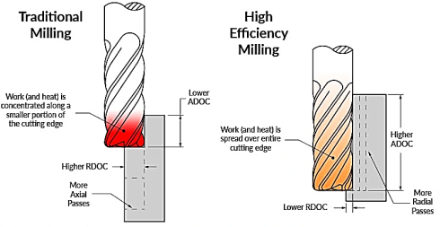
High-Efficiency Milling (HEM) is a novel machining strategy that employs the use of CAM to set cutting parameters and generate an efficient toolpath strategy. It focuses on a low RDOC and a high ADOC to maximize MRR while controlling chip load, tool engagement, and heat distribution.
Low radial DOC + Full Flute Axial DOC Concept
The below table draws a comparison between traditional milling strategy and HEM strategy. Please note the differences in cutting parameters:
|
Parameter |
Traditional Milling |
HEM Strategy |
|
Radial DOC (stepover) |
30 - 80% of tool diameter |
5 - 15% of tool diameter |
|
Axial DOC (cut depth) |
50 - 100% × tool diameter |
200 – 300 % of tool diameter |
|
Feed rate |
Moderate |
Lower |
|
Engagement angle |
High |
Controlled to stay < 90° (often < 60°) |
|
Result |
Higher tool load, lower life |
Lower heat, consistent wear, faster material removal |
Engagement-angle calculator for adaptive toolpaths
As an example, in CNC machine of 12 mm carbide end mill in 4140 Steel, the following cutting parameters would be preferrable:
Tool diameter: 12 mm
Radial DOC: 1.2 mm (10% of tool diameter)
Axial DOC: 24 mm (2× tool diameter)
Feed per tooth (fz): 0.03 mm
RPM: 4000
Feed rate: 480 mm/min
Engagement angle: 35 - 45°
Troubleshooting: When DOC Settings Go Wrong
An expert machinist should be able to diagnose the any defects in the machining quality and then apply corrective measure. Some of the common defects and their troubleshooting is discussed below:
Tool Chatter
High-pitched vibrations, waviness in cut and tool wear are characteristic of tool chatter. These can be prevented by reducing axial DOC, selecting a stiffer tool (e.g carbide tool), and using a rigid tool holder.
Burning Or Blue Chips
Burning or blue chips indicate overheating. An abundant use of coolant and use of chip breakers can prevent it.
Poor Surface Finish
Rough, torn, or scalloped surface finish can be prevented by decreasing radial DOC
Maintaining a constant feed per tooth. Use of climb milling can give a better surface integrity.
Other Key Cutting Parameters in CNC Machining
In addition to the triad of feeds – speeds and DOC, there are several other cutting parameters which influences the MRR and quality parameters in CNC machining. There is a brief detail about these parameters below:
Radial Cut Width (Stepover)
Also known as stepover, this is the width of the cut made in the radial direction. It impacts surface finish, tool engagement angle, and chip load.
Tool Engagement Angle
It is the angle over which the tool is in contact with the material. High engagement angle increases heat. That is why lower angles are used in HEM.
Rake and Relief Angles
These are part of tool geometry. They affect chip flow and tool cutting efficiency.
Cutting Fluid Strategy
Optimal coolant flow helps in mitigating excessive heat buildup. It indirectly affects the surface finish.
Spindle Power & Torque Limits
There should be a compatibility between machine capabilities like spindle power and torque with feed and speeds.
Toolpath Style
Toolpath style impacts tool wear, chip load and thermal control.
How Does Depth of Cut Influence Other Machining Factors?
DOC influences factors like tool life, surface finish, machine load and chip control. A high DOC will put more pressure on both the tool and the machine motor. If it is not optimum, it will reduce tool life, roughen surface finish and increase machine load.
Conclusion
At TUOFA Precision CNC we have an experienced machining team and compliance with international standards. We adopt the best industrial practices like HEM and ensure that our depth of cut remains optimum. As a result, we deliver our customer a great quality of surface finish while enhancing our productivity. That is why we can easily fulfil our commitments of quality and timely delivery.
FAQs
What is a good starting depth of cut for beginners?
Start with a 25% tool diameter DOC and gradually increase it to the optimum level.
Can I copy DOC charts from aluminum to stainless steel?
Yes, the charts in this blog are good to copy and use.
 Subtractive Manufacturing: Processes, Benefits & When to Choose It