Tel/WeChat:
  Email:
 Home
HomeMicron-Level 5-Axis CNC Machining for Humanoid Robot Components

 Published:Jan 21,2026
A representative case study showing how Tuofa CNC Machining manufactures high-precision humanoid robot transmission components in 17-4PH stainless steel. It highlights 5-axis CNC machining for tight tolerances (±0.005–0.01 mm).
At a Glance
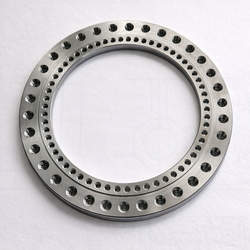
Tuofa CNC Machining made a high-precision transmission component used in a humanoid robot wrist/hand rotation joint. The robotic component was machined in 17-4PH stainless steel and required micron-level dimensional control prior to assembly. The client provided more than a dozen part designs; we selected the most difficult 1-2 ones as the initial proof-of-capability and completed design review, trial machining, verification, and customer validation in approximately two weeks.
- Robotic Material: 17-4 PH stainless steel.
- Tolerance target (pre-assembly): +/-0.005 to 0.01 mm on critical features.
- Process core: 5-axis CNC machining.
- Outcome: achieved ~0.01 mm capability on critical dimensions; customer confirmed functional suitability.
- Applications: used in the robotic joint, which allows 360 ° movement.
(Just for reference)
Confidentiality Notice: For 20 years, Tuofa CNC Machining has valued its reputation and will never, ever, disclose a client's product/design information in any way. The numerical values and details shown in this case study are taken from industry standards and are not from actual client information. This case study aims to illustrate our machining experience and capabilities, as well as the details of the services we provide.
Project Background
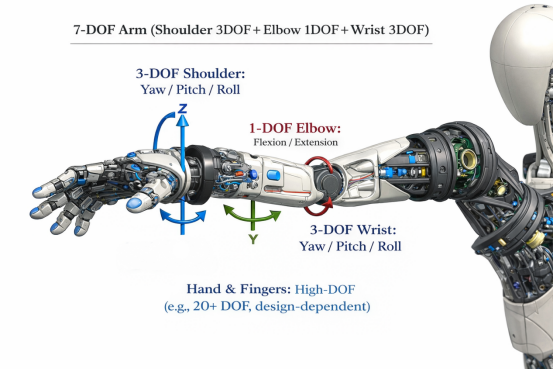
Humanoid robots impose unusually strict requirements on joint transmission parts because precision errors accumulate through the kinematic chain. A small deviation at a wrist joint can amplify into noticeable end-effector positioning error, uneven bearing load, increased backlash, or accelerated wear in mating components. For this reason, robotic joint designs typically specify tight limits on concentricity, runout, flatness, and bearing-seat fits, often at the micrometre scale.

To frame the tolerance level, ISO 286 defines International Tolerance (IT) grades for size tolerances. Micron-level bands such as 5-10 micrometres are comparable to the tighter IT grades for common shaft and bore sizes. The table below provides illustrative values calculated from the ISO 286-1 tolerance unit formula for selected nominal diameters (values shown as total tolerance band in micrometres).
|
Nominal diameter D (mm) |
IT5 band (µm) |
IT6 band (µm) |
IT7 band (µm) |
Typical use |
|
10 |
7 |
10 |
16 |
Precision fits for shafts/bores |
|
30 |
10 |
14 |
23 |
Precision fits for shafts/bores |
|
50 |
12 |
17 |
27 |
Precision fits for shafts/bores |
Note: The band shown is the total tolerance width for the IT grade at the selected size range. Equivalent +/- tolerance is approximately half of the band.
Component and Functional
The application is a 360-degree hand rotation axis in a humanoid robot. At system level, the wrist rotation joint is commonly realized through the interaction of:
- Mechanical shaft: provides the rotation axis and carries torque and bending loads.
- Bearings: support rotation with controlled friction and maintain radial/axial positioning.
- Transmission components: transfer torque between actuator and the rotating hand axis (e.g., gear interfaces, couplings, or reducers).
Technical Challenges
The project constraints combined tight tolerances, difficult material behavior, and multi-feature datum requirements. Key technical challenges included:
- Micron-level tolerance band: critical dimensions required +/-0.005 to 0.01 mm control prior to assembly.
- Feature-to-feature coherence: concentricity and runout control between multiple diameters across the shaft.
- 17-4 PH machining and stability: controlling tool wear, heat input, and potential distortion.
- Surface integrity: burr-free edges and stable surface finish on bearing and sealing interfaces.
- Verification complexity: measurement uncertainty becomes a material fraction of the tolerance at 5-10 microns.
Manufacturing Process
We executed a structured workflow from design review through validation.
1) Process Planning
The client supplied more than a dozen design options. We selected the most challenging 1-2 ones as the initial target to de-risk the program early. The engineering review identified critical-to-quality (CTQ) features and established a datum strategy to minimize stack-up errors.
- CTQ features identified: bearing seat diameter(s), mating shoulder flatness, shaft runout, threaded feature position, and interface perpendicularity.
- Datum strategy: primary datum on a stable cylindrical reference; secondary datum on an axial face; tertiary datum on a keyed/flat feature.
- Machining route: roughing -> stress stabilisation -> semi-finishing -> finish machining -> deburr -> final inspection.
2) 5-Axis Machining Strategy
To keep micron-level accuracy, we machined as many critical features as possible in one setup on a 5-axis CNC machine. This reduces re-clamping error and keeps all features aligned to the same datums.
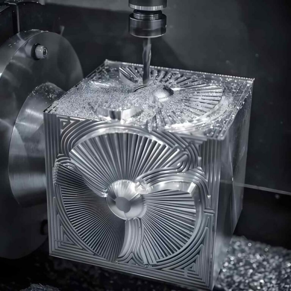
- Tooling: premium carbide tooling with controlled wear; finishing passes sized to minimize deflection.
- Thermal control: managed coolant strategy and stable shop temperature to reduce thermal drift.
- Programming: CAM simulation to avoid collisions and ensure continuous tool engagement where possible.
3) Surface Finishing
After semi-finishing to leave a controlled machining allowance, final passes were executed with conservative parameters and consistent toolpath direction to improve surface integrity. Deburring was performed using a controlled method to avoid edge roll or dimensional change on CTQ edges.
- Final sizing: dedicated finishing tools for bearing seats and mating diameters.
- Edge condition: burr-free requirement at functional interfaces; visual and tactile inspection criteria.
- Thread feature: thread hole machining and verification using gauges.
4) Metrology and Acceptance
Measurement strategy was designed around measurement uncertainty relative to tolerance. In-process checks controlled drift before final finishing, and final acceptance relied on a complete inspection report.
Results and Client Feedback
Within approximately two weeks (design confirmation -> trial -> verification -> customer validation), we achieved pre-assembly dimensional capability at approximately 0.01 mm on critical dimensions, consistent with the client’s stated requirement band. The client confirmed the part met functional needs in their assembly.
- Achieved capability: approximately 0.01 mm on key pre-assembly dimensions.
- Program impact: early success on the hardest design reduced downstream risk for the remaining design variants.
Conclusion
To protect customer IP, this case study uses representative, standards-based examples rather than any client-specific design data. What it shows is Tuofa CNC Machining’s core strength: producing high-precision robotic transmission parts with 5-axis CNC to strict demands. We support customers with an engineering-led workflow—from manufacturability review and trial machining to verified prototypes and small-batch production—without compromising confidentiality.
 The Best Process for High-Precision Thin-walled Aluminum Cylinder Parts